Download
1 / 18
180 likes | 186 Vues
Learn about the theory of operation and principles of the PD800W Cordless Phasing Tester. This equipment overview provides specifications, procedures, and features of the tester. Explore how it compares phase angles and displays voltage relationships in real-time. Understand the different switch positions and their functions. The tester also allows for testing phase sequences.

E N D
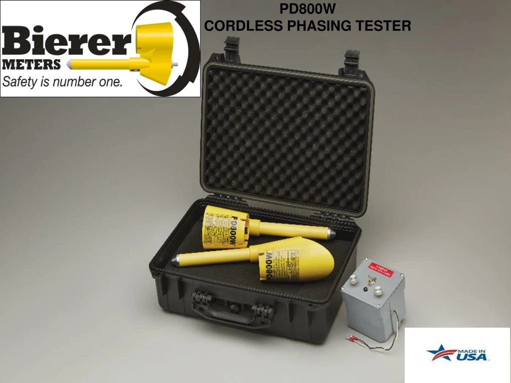
PD800W CORDLESS PHASING TESTER
OVERVIEW • Theory of Operation & Principles • Introduction to the PD800W • Equipment Overview/Specifications • Procedures • Features
Theory of Operation & Principle • In the “DEG” switch position, the PD800W compares the Phase Angle between the Reference Probe and the Meter Probe in Real-Time. • The resultant between the two measurements is displayed as a numerical number in Degrees on the Meter Probe and as LED lights (White, Blue, Red) below the number. • In the “URD” (Underground Residential Distribution) or “OH” (Overhead) switch position, the PD800W compares the Phase Angle between the Reference Probe and the Meter Probe in Real-Time and simultaneously displays a nominal voltage relationship (Phase-to-Phase) as well as the LED lights (White, Blue, Red) below the number.
Equipment OverviewMeter Probe Five Position Switch Delta/Wye Light 240 Degree Light 120 Degree Light 0 Degree Light Phase Angle Display
Equipment OverviewReference Probe Five Position Switch • The White LED on the Reference Probe will be “ON” if the voltage or electrical field is equal to or greater than the threshold values below: • DEG Switch Position 30VAC • URD or OH Switch Position Approx. 300VAC
Equipment Overview Selector Switch Position and Function • “OFF” – Unit is off for storage or transit. • “DEG” – For Phase Angle measurements (all traditional phasing applications) between the Meter Probe and Reference Probe on 3-Phase Secondary, URD, Overhead/Transmission systems. Make direct contact from capacitive test points to 69kV Phase-to-Ground. Non-Contact (minimum approach distances) for any voltages above 69kV Phase-to-Ground. • “URD” – For nominal voltage readings in URD systems or applications 10ft. or less above Earth. Direct contact from 4kV to 51kV, not for use on capacitive test points. • “OH” – For nominal voltage readings in Overhead systems or applications 20ft or higher above Earth. Direct contact from 4kV to 51kV. • “TEST” – Performs an internal self-test (displays “510”), also displays approximate internal battery voltage, i.e. 080 = 8VDC.
Equipment Overview Meter Probe Phase Lights Indications Note:The Meter Probe colored lenses (White, Blue, Red) can be manually moved or swapped with other lenses to display or coordinate the color sequence per the Utilities preference. Example: Instead of a White, Blue, Red (OEM) sequence, a Utility can make the sequence Blue, White, Red or Red, White, Blue, etc. • 0° – Indicates an In-Phase condition • 120°– Indicates an Out-of-Phase condition of 120°. • 240° – Indicates an Out-of-Phase condition of 240°. • D/Y – Indicates a Delta/Wye transformation, i.e. +/-20° phase shift in conjunction with one of the other three phase LED lights.
Procedures • (Continued) Step #7, if the Meter Probe reading is not one of or near the nominal 3-Phase readings, i.e. 0°, 120°, 240° and some multiple of 30° as demonstrated in the image below right, then the Reference and Meter Probe is phasing across a Delta/Wye transformation. • A blinking Yellow “D/Y” light indicates a Delta/Wye transformation (multiple of 30° phase shift) in conjunction with one of the other phase indicator lights. • Note: The White Light on the Reference Probe will always be on if the unit sees at least 30VAC, in direct contact or electrical field. The White Light must be present to ensure proper operation of the PD800W. The D/Y yellow LED activates if the phase angle deviates +/- 20° from any one of the three nominal readings
Procedures • With both Probes still in the DEG switch positions, test phase sequence. Note: Phase sequence is the order in which the voltages of a three phase system rise and fall. Only two sequences are possible, normally referred to as a “Positive” and “Negative” sequence, or a “Clockwise” and “Counter-Clockwise” sequence. • However, there are three different physical connections as demonstrated on the following page, to achieve each sequence. Any one of the phases of a three phase system may be assigned the status of “Leading” phase. This convention is currently left up to the discretion of the electric utility.
ProceduresTesting Phase SequenceDEG Switch Position • Sequence (A-B-C)(1-2-3) • A-B-CA-B-C-A-B-CA-B-C • B-C-A B-C-A-B-C-A-B-C-A • C-A-B C-A-B-C-A-B-C-A-B • Sequence (C-B-A)(3-2-1) • C-B-AC-B-A-C-B-A-C-B-A • B-A-C B-A-C-B-A-C-B-C-A • A-C-B A-C-B-A-C-B-A-C-B
ProceduresTesting Phase SequenceDEG Switch Position 9. With both Probes still in the DEG switch positions, test for phase sequence while using Step #7 criteria. • Touch or approach A(1) phase with the Reference probe • Touch or approach B(2) phase with the Meter probe • Sequence (A-B-C)(1-2-3) will be indicated by a nominal 120° and the Blue LED will be on • Sequence (C-B-A)(3-2-1) will be indicated by a nominal 240° and the Red LED will be on
ProceduresPhase-to-Phase Out-of-Phase Voltage ReadingDirect Contact URD and OH – 4kV-to-69kV • Obtained by touching one phase conductor with the Reference Probe and another phase conductor with the Meter Probe
ProceduresPhase-to-Phase In-Phase Voltage ReadingDirect Contact URD and OH – 4kV-to-69kV • Obtained by touching the Reference Probe and Meter Probe to conductors of the same phase
ProceduresPhase-to-Ground ReadingDirect Contact URD and OH - 4kV-to-69kV • Meter Probe or Reference Probe may be used as a stand alone direct contact digital Voltage Detector. • When using the Meter Probe in this manner the Reference Probe must be switched off. • When using the Reference Probe in this manner, the nominal voltage will be displayed on the Meter Probe. Note: Make sure both probes are in the same selector switch position.
ProceduresReference Probe as a Voltage DetectorDirect Contact Deg, URD & OH – 120V-to-69kV • Obtain reading by touching the energized conductor or capacitive test point. The White LED will be on if the voltage is equal to or greater than the threshold values below: • Deg position 30V • URD or OH Approx. 350V
FeaturesPD800WCORDLESS PHASING TESTER • Saves Money – Less Time • Improves User Safety – No interconnect cable required • Multi-Function 4 Meters in one: 1. Phasing Tool 2. Phase Sequence Indicator 3. Phase Angle Indicator 4. Voltage Detector • Wide Operating Voltage Range: - 120V-to-800kV
FeaturesPD800WCORDLESS PHASING TESTER • Application Flexibility in the Field • Allows Uniformity of Equipment In The Field, Transmission, Substation, Distribution • Requires No Ranging, Multipliers or Extension Resistors, Universally Phases on Any System; Including Capacitive Test Points