Download
1 / 43
570 likes | 996 Vues
Seismic data inversion. Enrico Pieroni Ernesto Bonomi Emma Calabresu () Geophysics Area CRS4. The Art of Inverse Problem inferring model parameters from output data. Inverse problems are among the most challenging in computational and applied science and have been studied extensively.

E N D
Seismic data inversion Enrico Pieroni Ernesto Bonomi Emma Calabresu () Geophysics Area CRS4 1
The Art of Inverse Probleminferring model parameters from output data • Inverse problems are among the most challenging in computational and applied science and have been studied extensively. • Although there is no precise definition inverse problems are concerned with the determination of inputs or sources from observed outputs or responses. • This is in contrast to direct problems, in which outputs or responses are determined using knowledge of the inputs or sources. 2
Presentation outline “Gauss-Newton and full Newton methods in frequency-space seismic waveform inversion” Pratt, Shin, Hicks Geohpys.J.Int. (1998) 133, 341-362 “High resolution velocity model estimation from refraction and reflection data” Forgues, Scala, Pratt SEG 1998 “Seismic Waveform inversion in the frequency domain” Pratt, Geophysics Jan 11, 1999 “Nonmonotone Spectral Projected Gradient Methods in Convex Set” 1999, Birgin, Martinez, Raydan • inversion framework • mathematical framework • steepest descent optim. • lagrangian approach • optimization loop • newton optimization • conjugate direction opt. • 1d optimization • constrained optimization • test cases “Multiscale seismic waveform inversion” Bunks, Saleck, Zaleski, Chavent Geohpysics (1995) 60, 1457-1473 “Nonlinear inversion of seismic reflection data in a laterally invariant medium” Pica, Diet, Tarantola, Geohpysics (1990) 55, 284-292 “Pre-stack inversion of a 1D medium” Kolb, Collino, Lailly IEEE (1986) 74, 498-508 3
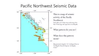
Inversion framework • Parameters: NxNyNz unknowns to recover: the velocity field c(x,y,z) • Observed data/measurements: recorded data at a reference depth STACK(x,y,t) = P(x,y,z=0,t). • Simulated data: wave-field propagation imposed by the acoustic wave equation using some trial velocity field • Inversion: find the velocity field that minimizes some measure of the misfit between observed and simulated data We solved the inverse problem with a single shot acquisition. The generalization to multiple shots is straightforward and can result in a better inversion. 4
Mathematical framework • measureSTACK(x,y,t) at same reference level z=0, produced by a single source • try a guessc(0)(x,y,z) for the velocity field • solving the acoustic wave equation, simulate the pressure field over the entire spatial domain (with adequate B.C. and I.C.) • evaluate the error or cost function and if necessary its derivatives (cumbersome) • update iteratively the velocity field, with the intent to minimize the error function • iterate this procedure up to a fixed “error threshold” 5
Steepest descent optimization • The velocity updating technique is usually based • on local informations, e.g. the gradient: • Fixed point = minima • problem: avoid local minima 6
Lagrangian approach • Constrained minimization problem adjoint field A sort of wave equation with source term = residual error Wave equation Back in time! From P and l evaluate the gradient PROBLEM: time alignment! 7
FMod BMod AdjMod Optimization loop do it=0, nit-1 ! call FMod do step = 0, nt-1 ! call BMod call LoadMeasField call AdjMod call PartialGrad call PartialCostF ! end do call Optimizer ! end do Record data at z=0 & on the boundaries Use information on the boundaries to backpropagate field P Load observed data With real and simulated measurements build the source term and solve for the adjoint field l Evaluate partial cost function and gradient Update velocity field Inner loop: align in time both direct and adjoint fields to perform in-core gradient evaluation 8
Newton optimization • The optimization procedure can use also information from the Hessian (second derivative matrix) but this is very expensive for both computational (# direct propagation = # parameters) and storage requirements ( [NxNyNz]2 )! • E.G. Newton, Quasi-Newton or Gauss-Newton methods: • Thus, aiming to a 3D reconstruction, we decided to only use the gradient. 9
Optimization techniques storage convergence 10
Conjugate direction optimization • To achieve better convergence we studied different conjugate direction algorithms: • [1] Fletcher-Reeves • [2] Polak-Ribiere • [3] Hestenes-Stiefel • (but we have not observed sensible differences) [1] [2] [3] 11
1D optimization • At each iteration step, for each fixed direction d and velocity c, find a scalar asuch that the resulting error function (depending now on a single real parameter) • be minimum, • E.G. by line search, bisection, generalized decreasing conditions 12
Constrained optimization • Because of the box constraints over the velocity, • we are forced to adopt the projected conjugate gradient: 13
Test cases nx = 116 nz = 66 nt = 270 dx = 3. dz = 3. dt = 0.00065 thick_x = 0 thick_z = 0 rec_thick_x = 1 rec_thick_z = 1 z_record = 4 Nopt = 20 Niter = 100 We will consider inversion of small 2D synthetic data-sets. For a better tuning of the algorithms we used velocity field with no lateral variations, but the code is genuine 2D. 14
Target: piecewise constant function Very good result, small changes after 140 iterations ... Initial guess: straight line 15
Log ! The cost function decreases of about 4 orders of magnitude. The steepest slope is obtained in the first ~20 iterations. A second sudden jump comes as the velocity gets the second ridge! 16
Target: piecewise constant function After ~10 iterations we get the first ridge ... Initial guess: straight line 17
We see the steepest slope in the first ~10 iterations, a ‘plateau’ seems to follow! 18
We take one of the last iterated field (#11) and freeze the gradient of the first (20) layers In ~20 iterations we reach both the first and the second ridges! 19
Iterated velocity field Target: piecewise constant function Things goes wrong if the low frequency trend is not included in the initial guess ... Initial guess: straight line but it does not matches the ‘trend’ 21
Here we start from #2 of previous iterations ... Freezing the first 20 layers, the 1st discontinuity gets worse but we better recover the 2nd one ... 23
Initial guess: straight line Target: parabola Good! After ~170 iterations things does not change too much! 25
Log ! 3 orders of magnitude decreasing! Steepest slope in the very first (~5) steps 26
In ~10 iterations we get a really good result! Target: parabola We start from the previous velocity field (#60) and freeze the gradient at the first layers (#20) 27
In the first ~8 iterations we have the steepest slope ... 28
Iterated velocity field Initial guess: straight line Target: parabola + sin Nice! The greatest part is done in the first ~100 iterations! 29
Cost Function Log ! As observed, the big is done in the first ~100 iterations! 30
Not good as before: we only get the medium trend! Target: parabola + sin We start from a previous iteration (#20) and freeze the gradient at the first (20) layers 31
Some preliminary conclusions • The main problem is the presence of a large number of local minima. To get rid of them is possible to linearize the direct model (eg Born approx.), to have a convex cost function • or adopt some multi-scale approach: • large to small spatial scale, or • low to high time frequencies but: loose refracted/multiply reflected waves, ecc. ecc. but: the ultra-low frequency (the velocity field trend) components don’t produce reflected waves, thus must be already present in the initial guess. 33
Time versus Frequency Domain The advantage of the time domain is the intuitive comprehension of the involved fields and results • Advantages of the time frequency domain • high data compression rate (~10) • uncoupled problems in embarassing parallelism • large to small spatial scale approach, inverting separately small and large frequenciesquickest and scalable approach 34
Extra time! 35
Spectral conjugate gradient • Spectral Conjugate Gradient Method • the advantage is that in this way the conjugate direction (- g) contains some explicit information on the Hessian matrix. 36
Modified Nonlinear Conjugate Gradient • In geophysic application, the number of parameters is very large, this motivates the choice of a conjugate gradient minimization algorithm • Without uphill movements (a<0) in the line search procedure, none optimization method will prevent the trapping inside the local minima 37
Line search (a>0) • In our approach a can be either positive, describing a movement in the descent direction of pk, or negative. • For a negative, the line search is similar 38
Analytical 1D example • very noisy function, presenting oscillations up to small scales (many local minima) • after 7 steps both Wolfe conditions are satisfied Allowing a<0, the algorithm can visit and leave most local minima 39
Analytical 2D example • the function is a sum of a simple convex quadratic and low-amplitude high frequency perturbation (N=2) • after 8 steps both Wolfe conditions are satisfied Allowing a<0, the algorithm can visit and leave most local minima 40
Analytical 32D example • same function as before, with N=32 • standard gradient based minimization methods are not satisfactory with such a noisy function • on nontrivial analytical examples, our approach converges quickly towards the global minimum 41
Number of parameters The number of parameters plays a crucial role in the choice of the algorithm to minimize the cost function j(p) in the parameter space Without uphill movements in the line search procedure, none optimization method will prevent the trapping inside the local minima The landscape of the cost function presents many local minima storage convergence 42
Number of parameters • The number p of parametersimpacts on the choice of the optimization strategy: • for very small p the gradient can be computednumerically • for small p, use the gradient and the Hessian to compute the search directions • exact Hessian (Newton) • approximation of the Hessian as the iteration progresses (Quasi-Newton). • for large p, use only the gradient to compute the search directions • nonlinear conjugate gradient • for very large p, use stochastic methods • simulated annealing 43