Download
1 / 40
970 likes | 1.67k Vues
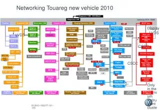
In-Vehicle Networking. Lecture 1 Introduction to CAN (Controller Area Network) BAE 5030 – 363 Spring 2009 Instructors: Marvin Stone Biosystems and Agricultural Engineering Oklahoma State University. Automotive Body Network. Hierarchical networks are here today. VW Phaeton

E N D
In-Vehicle Networking Lecture 1 Introduction to CAN (Controller Area Network) BAE 5030 – 363 Spring 2009 Instructors: Marvin Stone Biosystems and Agricultural Engineering Oklahoma State University BAE 5030-363
Automotive Body Network BAE 5030-363
Hierarchical networks are here today • VW Phaeton • Electrical parts: 11,136 • Communication: 61 ECUs in total • External diagnosis: 31 ECUs via serial communication • Optical bus for high bandwidth Infotainment-data • sub-networks based on proprietary serial bus • 35 ECUs connected by • 3 CAN-busses • sharing approximately 2500 signals • in 250 CAN messages BAE 5030-363
CAN applications are broad • 63 ECUs • 33 CAN nodes • 2 250 k CAN Networks Ntech RT500 Fertilizer Applicator BAE 5030-363
Costs and Speeds for Automotive Networks D2B, MOST token ring optical bus 25.6M Byteflight optical bus 2M TTx (in definition) time triggered fault tol, dependable 2x2 wire Speed [bit/s] ISO 11783 CAN-C event triggered Quad wire 1M 125K CAN-B event triggered fault tolerant dual wire J1850 pier to pier prioritized messages 20K LIN master-slave single wire bus no quartz 1 10 2 4.5 incremental cost per node [$] BAE 5030-363
What is CAN? • CAN = Controller Area Network • Serial data communications protocol for real-time application using a multiple access bus • Messages have assignable priority • most critical can dominate during heavy load • Messages are short (controlled length) • opportunities to insert a new message come often • CAN provides multiplexed serial communications • Reduction in wiring complexity • Better information sharing • All communications share the same communication path • Low probability of an undetected error • 4.7 x 10⁻¹¹ x message error rate • For a message error rate of 25/sec: 1 undetected error per 10,000 hours operation BAE 5030-363
An overview of CAN based networking • Elements of the CAN protocol • Message components • Identifier / Data • Bus Access - Arbitration / Prioritization • CSMA/CR (carrier sense multiple access / collision resolution • Bitwize priority access strategy • Non-destructive collisions • Error Detection / Error Confinement • Filtering • Other features • In Frame Acknowledgement • RTR BAE 5030-363
Capacity Comparison BAE 5030-363
Capacity and Performance (Based on 250 KBaud) • Use of bus bandwidth by messages • 100 messages per second (10 ms repetition) =5% • Torque/Speed control on engine • Hitch control • 10 messages per second (100 ms repetition) =0.5% • Throttle position • GPS Lat/Lon data • Implement application rate control (process data) • 1 message per second (1s repetition) =0.05% • Display updates • System status BAE 5030-363
Message latency (Based on 250 KBaud) • 134 bit message • @ 4m s per bit = 536m s = 0.5 ms per message max • Highest priority message • must wait no more than ~0.5 ms • Low priority messages • must wait till higher priority messages clear • latency may be long at high bus loads BAE 5030-363
Harness Hell! BAE 5030-363
Conventional Wiring (No Bus) Serial Communication Links BAE 5030-363
A Simple CAN Application (Serial Bus) BAE 5030-363
Multiplexed communication BAE 5030-363
Typical ECU Components BAE 5030-363
ECU Connection to the bus ECU 1 ECU 2 CAN_H CAN_H CAN_L Terminator Terminator CAN_H CAN_L BAE 5030-363
CAN - continued • Developed by Bosch GmBh (See http://www.semiconductors.bosch.de/pdf/can2spec.pdf) • About 1986, Version 2.0 in 1991 for auto apps. • Version 1.2 (Equivalent to 2.0A) • 11 bit ID (not interoperable with 29 bit 2.0b) • Version 2.0 (2.0A + 2.0B) • 2.0B - 11 and 29 bit ID • 11 and 29 are compatible on same bus • 11 bit only 2.0B is called 2.0B passive • 29 bit (and 11bit) 2.0B called 2.0B active • CAN provides only Data Link functions • Media access control • Logical link control BAE 5030-363
Components of a “CAN Protocol” To form a complete communications system you need more than CAN ISO 7498 – Open Systems Interconnection (OSI) BAE 5030-363
Network Protocols based on CAN • SAE J1939 • Heavy Duty Diesel Systems • On-Highway Truck • Agricultural Equipment • Construction Equipment • Generator Sets • ISO 11783 • Ag and Forestry Equipment • NMEA 2000/IEC 61162-3 • Marine / GPS / Navigation • CANopen • Broad industrial applications - (CiA) • EN 50325-4 • DeviceNet • Industrial automation – PLCs (Allen Bradley) • CAN Kingdom • Meta protocol - (Kvaser) BAE 5030-363
CAN Arbitration Physical Signaling Example (ISO 11878) Lower numbered identifiers assume higher priority BAE 5030-363
Consequences of identifier prioritization in CAN • Unique Identifiers • Developer must assure all identifiers within a bus system are unique • Resyncronization • CAN controllers assure message transmissions always start at the same time among controllers on the bus • All messages queued are sent simultaneously • System appears to have one large queue where highest priority message is sent first BAE 5030-363
CAN Frame Components 11 bits or 29 bits CAN Frame (up to 134 bits) 0 to 8 bytes (0 to 64 bits) Identifier Data Start Serial bit stream BAE 5030-363
CAN Frame Format - CAN 2.0B CAN Frame (up to 134 bits) 0 to 8 bytes (0 to 64 bits) 11 bits or 29 bits Identifier Data BAE 5030-363
Acknowledgement • In-Frame acknowledgement • Any receiver of a message that receives a message correctly asserts a dominant acknowledge bit within the frame of the message being sent. • Transmitter can know message was received by some receiver • Further message confirmation must be built at a higher level in the protocol • Transmitter alone on a bus will go bus OFF • Receiver with an error • Transmits an error frame immediately after the message causing a Frame Error for all receivers BAE 5030-363
Remote transmission request (RTR) • Request message hardware feature • Allows setting a bit of an identifier to request a controller with a matching identifier to send the message • Can allow a response of a queued message without CPU interaction • Commonly not exploited in higher level standardized protocols BAE 5030-363
Error Detection • 5 Error Types Detected • Bit Error (Sent bit doesn’t match monitored bit) • Stuff Error (more than 6 successive in one state) • CRC error • Form Error • Acknowledge Error • Probability of an undetected error • 4.7 x 10⁻¹¹ x message error rate • for a message error rate of 25/sec, 1 undetected error per 10,000 hours operation BAE 5030-363
Message Filtering - Example Accept if: (ID AND MASK) XOR MATCH = 0 10111100100 IDENTIFIER 11100000000 1 = Care, 0= Don’t Care MASK 10100000000 = ID AND MASK Pattern must match 10100000000 MATCH 00000000000 = (ID AND MASK) XOR MATCH BAE 5030-363
Bus Timing • Bus bit rate is controlled by bit time • 1 MBaud 1 ms/bit • 250 KBaud 4ms/bit • Bit time is controlled by • Time Quanta (TQ) • Bit segment settings (no. of TQ per bit) • Bit Time = TQ * (Sync_Seg + Prop_Seg + Phase_Seg1 + Phase_Seg2) BAE 5030-363
Bit Timing Microchip CAN Seminar, 2006 BAE 5030-363
Propagation segment • Twice the sum of Driver, cable , and comparator delay (See Microchip AN754) • Propagation delay of cable • Typically 60-70% of c for 120 Ohm cables • Example: • Driver/Comparator delays – See datasheet • 50 ns tprop= 2⋅(tcmp + tbus+ tdrv) BAE 5030-363
Error handling Microchip CAN Seminar, 2006 BAE 5030-363
Collaborative Error Frame Generation • Error Frames are generated for any error detected by a CAN protocol controller • CAN protocol controller responds with an error echo if another node generates an error frame Microchip CAN Seminar, 2006 BAE 5030-363
CRC errors Microchip CAN Seminar, 2006 BAE 5030-363
Acknowledge Errors Microchip CAN Seminar, 2006 BAE 5030-363
Form Errors Microchip CAN Seminar, 2006 BAE 5030-363
Stuff Errors Microchip CAN Seminar, 2006 BAE 5030-363
Bit Errors Microchip CAN Seminar, 2006 BAE 5030-363
System Fault Confinement Microchip CAN Seminar, 2006 BAE 5030-363
System Fault Confinement Microchip CAN Seminar, 2006 BAE 5030-363
System Fault Confinement Microchip CAN Seminar, 2006 BAE 5030-363