Download
1 / 165
1.88k likes | 2.41k Vues
The 8051 Microcontroller. Intruduction. Microprocessor (uP)(MPU) A uP is a CPU on a single chip. Components of CPU ALU , instruction decoder, registers , bus control circuit, etc. Micro-computer (u-Computer) small computer

E N D
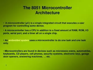
Intruduction • Microprocessor (uP)(MPU) • A uP is a CPU on a single chip. • Components of CPU • ALU, instruction decoder, registers, bus control circuit, etc. • Micro-computer (u-Computer) • small computer • uP + peripheral I/O + memory specifically for data acquisition and control applications • Microcontroller (uC) • u-Computer on a single chip of silicon
uP vs. uC • A uP • only is a single-chip CPU • bus is available • RAM capacity, num of port is selectable • RAM is larger than ROM (usually) • A uC • contains a CPU and RAM,ROM ,Peripherals, I/O port in a single IC • internal hardware is fixed • Communicate by port • ROM is larger than RAM (usually) • Small power consumption • Single chip, small board • Implementation is easy • Low cost
uP vs. uC – cont. • Applications • uCs are suitable to control of I/O devices in designs requiring a minimum component • uPs are suitable to processing information in computer systems.
uP vs. uC – cont. • uC is easy to use and design. • Only single chip can be a complete system • interfacing to other devices, • for example, motors, displays, sensors, and communicate with PC. • In contrast, similar system that builds from uP would require a lot of additional units, • such as RAM, UART, I/O , TIMER and etc.
uC is a Reusable Hardware • Logic circuit provides limited function for one single design. In order to change circuit’s functionality, we need to redesign the circuits. • uC can reprogram and change functionality of every port, input to output or digital to analog on the fly.
uCs • Many uCs are existing right now. • 8051, 68HC11, MSP430, ARM series, and etc. • We may widely divide it with how it is designed • RISC/CISC architecture. • What is the main difference between RISC/CISC? • Does it make any difference to our application?
Introduction to Microcontrollers Parts of computer: CPU, memory, I/O • CPU: Control and data path • Memory: Stores instruction and data • Input/output: Interact with the outside of computers
Microcontroller Components – Memory • Each memory location has a specific address • We must supply an address to access the corresponding location • R/W allows us to select reading or writing • Various types of memory for different functions and speeds Memory location 0 Memory location 1 address data Memory location n-2 Memory location n-1 r/w
Microcontroller Components – Memory • Read Only Memory - Memory that can only be read • Holds the program code for a microprocessor used in an embedded system where the code is always the same and is executed every time the system is switched on • Computer BIOS, boot-up information • Other types of Read Only Memory • Erasable Programmable Read Only Memory (EPROM) – Similar to ROM but can be erased (exposure to ultraviolet light) and reprogrammed • Electrically Erasable Programmable Read Only Memory (EEPROM) – more common that EPROM because it can be erased by the microprocessor • Flash Memory, Ferroelectric RAM (FRAM), Magnetic Random Access Memory (MRAM)
Microcontroller Components – Memory • Random Access Memory – used to store dynamic data when processor is running • Holds program code and data during execution • Can be accesses in any random order – unlike takes or disks • Some types of RAM • Static RAM (SRAM) – Uses transistors to store bits, fast SRAM is used for cache • Dynamic RAM (DRAM) – Uses capacitors to store bits, must be refreshed, smaller and cheaper than SRAM • Fast Page Mode (FPM), Extended Data Out (EDO) • Synchronous DRAM (SDRAM) – introduced in 1997 and replaced most DRAM in computers by 2000 • Double Data Rate (DDR SDRAM) – uses both clock edges found today in most computers • Direct Rambus DRAM (RDRAM) – somewhat of a flop
Microcontroller Components – CPU • Smart part • Processes instructions and data • All the parts of a microprocessor • Registers – fast memory used to store operands and other information • Condition register – positive/negative result • Exception register – overflow condition • Loop count register • Load-store architecture Register 0 data address Register 1 r/w Register n-1 inst ALU CPU
Microcontroller Components – I/O • Connection to the outside world • Examples • Analog to Digital Converter • Temperature Sensor • Display • Communications Circuit
Microcontroller Components – BUS • Group of wires used to transport information • CPU to Memory • Address bus • Data bus • CPU to I/O • Port mapped I/O – used when address space is limited, special instructions are needed for I/O • Memory mapped I/O – I/O looks like memory locations, easier to use and common in Reduced Instruction Set Computing (RISC)
Machine-level Execution Machine instruction: • A bundle of binary bits with certain formats • Only asks for simple operations • Assembly: textual notations of machine program Example: c = a + b; Machine execution: r1 ← mem(a) r2 ← mem(b) r3 ← ADD r1, r2 mem(c) ← r3
Major Instruction Types Arithmetic and logic: Add, subtract, multiply, divide; and, or, not, xor Data movement: transfer data between registers and/or memories Control: Branches and jumps
Processor Performance CPU Time = # Cycles × Cycle Time = # Instructions × CPI × Cycle Time CPI: Cycles per instruction
RISC vs. CISC RISC: Reduced Instruction Set computers RISC features: • Every instruction does a simple task • Fixed instruction length (usually 32 bits) • Data operations only applies to registers not memory • Use memory load and store instruction to move data • Use general purpose registers (usually 32) • Use simple ways of referencing memory words CISC: Complex Instruction Set computers
Embedded System Programming • Key factors in embedded programming • Speed – timing constraints, limited processing power • Code size – limited memory, power • Programming methods • Machine Code – bits • Low level language – assembly • High level language – C, C++, Java • Application level language – Visual Basic, Access • Levels of abstraction – factor out details to focus on few concepts at a time
Embedded System Programming • Why use C in embedded programming? • Ease of management of large embedded projects • Provides an additional level above assembly programming • Fairly efficient • Supports access to I/O • Why use assembly? • High speed, low code size • However, difficult to do a large project in assembly
Embedded System Programming • Bit is the smallest unit of information • Base 2 notation – two values • 1 – On, True • 0 – Off, False • Nibble • 4 bits – 16 possible values • 1 Hex character = 1 nibble • Byte, Word, Double Word • 8 bits, 16 bits, 32 bits • Some ambiguity
Embedded System Programming • Three most common forms of notation • Binary (base 2) – 0,1 • Decimal (base 10) – 0,1,2,...,9 • Hexadecimal (base 16) – 0,1,2,...,9, A,B,C,D,E,F • Can also use octal (base 8) • Converting between forms • Binary to Hexadecimal • Easy, every 4 bits is a hexadecimal character • 11000100 • 1100 0100 C 4
Binary to Decimal Conversion • Each bit represents an increasing power of 2 • When viewing a byte least significant bit is at the right • Words can be a little more confusing • Big-endian MSB is stored first • Little-endian LSB is stored first
Decimal to Binary Conversion • Subtract the highest power of 2 • Record a 1 in the corresponding bit location • Pad the remaining bit locations with a 0 • We will talk about signed binary later
8051 Basic Component • 4K bytes internal ROM • 128 bytes internal RAM • Four 8-bit I/Oports (P0 - P3). • Two 16-bit timers/counters • One serial interface CPU RAM ROM A single chip Serial COM Port I/O Port Microcontroller Timer
Block Diagram External Interrupts Interrupt Control 4k ROM 128 bytes RAM Timer 1 Timer 2 CPU OSC Bus Control 4 I/O Ports Serial RXD P0 P2 P1 P3 TXD Addr/Data
Other 8051 featurs • only 1On chip oscillator (external crystal) • 6 interrupt sources (2 external , 3 internal, Reset) • 64K external code (program) memory(only read)PSEN • 64K external data memory(can be read and write) by RD,WR • Code memory is selectable by EA (internal or external) • We may have External memory as data and code
Embedded System(8051 Application) • What is Embedded System? • An embedded system is closely integrated with the main system • It may not interact directly with the environment • For example – A microcomputer in a car ignition control • An embedded product uses a microprocessor or microcontroller to do one task only • There is only one application software that is typically burned into ROM
Examples of Embedded Systems • Keyboard • Printer • video game player • MP3 music players • Embedded memories to keep configuration information • Mobile phone units • Domestic (home) appliances • Data switches • Automotive controls
Three criteria in Choosing a Microcontroller • meeting the computing needs of the task efficiently and cost effectively • speed, the amount of ROM and RAM, the number of I/O ports and timers, size, packaging, power consumption • easy to upgrade • cost per unit • availability of software development tools • assemblers, debuggers, C compilers, emulator, simulator, technical support • wide availability and reliable sources of the microcontrollers
Comparison of the 8051 Family Members • ROM type • 8031 no ROM • 80xx mask ROM • 87xx EPROM • 89xx Flash EEPROM • 89xx • 8951 • 8952 • 8953 • 8955 • 898252 • 891051 • 892051 • Example (AT89C51,AT89LV51,AT89S51) • AT= ATMEL(Manufacture) • C = CMOS technology • LV= Low Power(3.0v)
Comparison of the 8051 Family Members WD: Watch Dog Timer AC: Analog Comparator ISP: In System Programable
EA/VPP ALE/PROG PSEN (INT0)P3.2 (INT1)P3.3 (WR)P3.6 (RD)P3.7 8051 Foot Print Vcc P1.0 1 40 P0.0(AD0) P1.1 2 39 P0.1(AD1) P1.2 3 38 P0.2(AD2) P1.3 4 37 8051 (8031) (8751) (8951) P0.3(AD3) P1.4 5 36 P0.4(AD4) P1.5 6 35 P0.5(AD5) P1.6 7 34 P0.6(AD6) P1.7 8 33 P0.7(AD7) RST 9 32 (RXD)P3.0 10 31 (TXD)P3.1 11 30 12 29 P2.7(A15) 13 28 (T0)P3.4 P2.6(A14) 14 27 (T1)P3.5 P2.5(A13) 15 26 P2.4(A12) 16 25 P2.3(A11) 17 24 P2.2(A10) XTAL2 18 23 P2.1(A9) XTAL1 19 22 P2.0(A8) GND 20 21
IMPORTANT PINS (IO Ports) • One of the most useful features of the 8051 is that it contains four I/O ports (P0 - P3) • Port 0 (pins 32-39):P0(P0.0~P0.7) • 8-bit R/W - General Purpose I/O • Or acts as a multiplexed low byte address and data bus for external memory design • Port 1 (pins 1-8):P1(P1.0~P1.7) • Only 8-bit R/W - General Purpose I/O • Port 2 (pins 21-28):P2(P2.0~P2.7) • 8-bit R/W - General Purpose I/O • Orhigh byte of the address bus for external memory design • Port 3 (pins 10-17):P3(P3.0~P3.7) • General Purpose I/O • if not using any of the internal peripherals (timers) or external interrupts. • Each port can be used as input or output (bi-direction)
Read latch Vcc TB2 Load(L1) P1.X pin Internal CPU bus DQ ClkQ P1.X M1 Write to latch TB1 Read pin Hardware Structure of I/O Pin
Hardware Structure of I/O Pin • Each pin of I/O ports • Internally connected to CPU bus • A D latch store the value of this pin • Write to latch=1:write data into the D latch • 2 Tri-state buffer: • TB1: controlled by “Read pin” • Read pin=1:really read the data present at the pin • TB2: controlled by “Read latch” • Read latch=1:read value from internal latch • A transistor M1 gate • Gate=0: open • Gate=1: close
Read latch Vcc Load(L1) P1.X pin Internal CPU bus DQ ClkQ P1.X M1 Write to latch Read pin Writing “1” to Output Pin P1.X TB2 2. output pin is Vcc 1. write a 1 to the pin 1 output 1 0 TB1
Read latch Vcc Load(L1) P1.X pin Internal CPU bus DQ ClkQ P1.X M1 Write to latch Read pin Writing “0” to Output Pin P1.X TB2 2. output pin is ground 1. write a 0 to the pin 0 output 0 1 TB1
Read latch Vcc Load(L1) P1.X pin Internal CPU bus DQ ClkQ P1.X M1 Write to latch Read pin Reading “High” at Input Pin 2. MOV A,P1 external pin=High TB2 • write a 1 to the pin MOV P1,#0FFH 1 1 0 TB1 3. Read pin=1 Read latch=0 Write to latch=1
Read latch Vcc Load(L1) P1.X pin Internal CPU bus DQ ClkQ P1.X M1 Write to latch Read pin Reading “Low” at Input Pin 2. MOV A,P1 external pin=Low TB2 • write a 1 to the pin • MOV P1,#0FFH 1 0 0 TB1 3. Read pin=1 Read latch=0 Write to latch=1 8051 IC
Vcc 10 K Port 0 P0.0 P0.1 DS5000 8751 8951 P0.2 P0.3 P0.4 P0.5 P0.6 P0.7 Port 0 with Pull-Up Resistors
IMPORTANT PINS • PSEN (out): Program Store Enable, the read signal for external program memory (active low). • ALE (out): Address Latch Enable, to latch address outputs at Port0 and Port2 • EA (in): External Access Enable, active low to access external program memory locations 0 to 4K • RXD,TXD: UART pins for serial I/O on Port 3 • XTAL1 & XTAL2: Crystal inputs for internal oscillator.
Pins of 8051 • Vcc(pin 40): • Vcc provides supply voltage to the chip. • The voltage source is +5V. • GND(pin 20):ground • XTAL1 and XTAL2(pins 19,18): • These 2 pins provide external clock. • Way 1:using a quartz crystal oscillator • Way 2:using a TTL oscillator • Example 4-1 shows the relationship between XTAL and the machine cycle.
C2 XTAL2 30pF C1 XTAL1 30pF GND XTAL Connection to 8051 • Using a quartz crystal oscillator • We can observe the frequency on the XTAL2 pin.
XTAL2 NC EXTERNAL OSCILLATOR SIGNAL XTAL1 GND XTAL Connection to an External Clock Source • Using a TTL oscillator • XTAL2 is unconnected.