Download
1 / 21
210 likes | 390 Vues
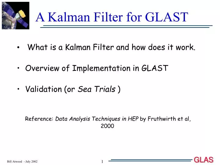
What is a Kalman Filter and how does it work. Overview of Implementation in GLAST Validation (or Sea Trials ) Reference: Data Analysis Techniques in HEP by Fruthwirth et al, 2000. A Kalman Filter for GLAST. Cx-x Cx-s Cs-x Cs-s.

E N D
What is a Kalman Filter and how does it work. Overview of Implementation in GLAST Validation (or Sea Trials ) Reference: Data Analysis Techniques in HEP by Fruthwirth et al, 2000 A Kalman Filter for GLAST
Cx-x Cx-s Cs-x Cs-s 1 z(k+1)-z(k) 0 1 Kalman Filter The Kalman filter process is a successive approximation scheme to estimate parameters Simple Example: 2 parameters - intercept and slope: x = x0 + Sx * z; P = (x0 , Sx) Errors on parameters x0 & Sx: covariance matrix: C = Cx-x = <(x-xm)(x-xm)> In general C = <(P - Pm)(P-Pm)T> Propagation: x(k+1) = x(k)+Sx(k)*(z(k+1)-z(k)) Pm(k+1) = F(dz) * P(k) where F(dz) = Pm(k+1) P(k) k+1 Cm(k+1) = F(dz) *C(k) * F(dz)T + Q(k) Noise: Q(k) (Multiple Scattering) k
k+1 Noise (Multiple Scattering) k Kalman Filter (2) Form the weighted average of the k+1 measurement and the propagated track model: Weights given by inverse of Error Matrix: C-1 Pm(k+1) Hit: X(k+1) with errors V(k+1) Cm-1(k+1)*Pm(k+1)+ V-1(k+1)*X(k+1) P(k+1) = and C(k+1) = (Cm-1(k+1) + V-1(k+1))-1 Cm-1(k+1) + V-1(k+1) Now its repeated for the k+2 planes and so - on. This is called FILTERING - each successive step incorporates the knowledge of previous steps as allowed for by the NOISE and the aggregate sum of the previous hits.
Kalman Filter (3) We start the FILTER process at the conversion point BUT… We want the best estimate of the track parameters at the conversion point. Must propagate the influence of all the subsequent Hits backwards to the beginning of the track - Essentially running the FILTER in reverse This is call the SMOOTHER & the linear algebra is similar. Residuals & c2: Residuals: r(k) = X(k) - Pm(k) Covariance of r(k): Cr(k) = V(k) - C(k) Then: c2 = r(k)TCr(k)-1r(k) for the kth step
3 Dimensional: Essentially GLAST is composed of 2 - 2D trackers however multiple scattering mixes x & y. This creates correlations between the two projections and hence the covariance matrix (C) has significant off (block) diagonal terms. Difference between two separate projections and 3D projection becomes increasingly important as BOTH the x & y become large. Calculation of c2 involves both x & y and their correlation The SMOOTHed c2 is not a true c2 as errors are correlated point to point (not so for the FILTER c2). However since the smallest errors (and hence the largest weights) are the measurement errors the difference between them is small. (Presently we use the SMOOTHed c2) Implementation in GLAST
c2 and the 1-Event Display Top View Y-Z View Blue Lines = +-c2 X-Z View 3 Views of a 1 GeV m+
End-to-End Testing Objective: Test if the implementation of the errors in the Kalman Filter Routines is Correct. Method: Use Monte Carlo m’s (KE = 100 MeV, 1 GeV, & 10 GeV) Provide the Kalman Filter with the correct energy (pb) Test: If Monte Carlo generation of multiple scattering is the same as that in the Kalman Filter AND the calculation of the covariance matrices is correct AND their usage is correct THEN we except <c2> ~ 1.0 independent of position and angle m’s generated over -1 < cos(q) < 0 Require > 15 Hits Allow Just 1 Track Cut-Off built into PR
The First Problem: c2 > 1 100 MeV - Normal Inc. Nhits = 36 <c2> = 1.6 Note: m’s generated with 100 MeV KE. This implies Etot = 205.7 MeV and pb = 151.4 MeV Red Line: c2 function with parameters as above
Partial Solution - Include Energy Loss 100 MeV m’s entering the Tracker exit with ~ 65 MeV First guess would give (assuming b ~ 1): ~ 22 MeV ( 50:50 for Si+C : W) Correcting for b ( = .85 const.): ~ 30 MeV Integrating over path ~ 35 MeV Implemented Bethe-Block Energy Loss in Kalman Filter (see results) <Nhits> = 36 <c2> = 1.25 Problem becomes small by 1 GeV
Second Problem: c2 Depends on Angles 1 GeV Muons Dependence on cos(q)
10 GeV Muons q < 45 All Angles q > 45
10 GeV Muons - f Dependence RED Line at <c2> = 1 Cluster Size Error Dependence Upper Plots: Error ~ (Size * sP) Resolution: Meas. Errors Lower Plots: Error ~ sP Where: sP = q < 45 q > 45
Third Problem: Tower Co-ordinate Issue: To include or not include theTower Co-ordinate as well as the Strip Co-ordinate. Inclusion controlled by the mapping of the measurements onto the parameters and visa-versa. (usually called the H matrix). Reason not to include: 1) When results examined on a scale commensurate with bin size (Tower) binning effects appear. 2) Slight pull of fit toward center of tower at normal incidence. 3) Masks the c2 behavior of the strip co-ordinate. With Tower Co-ordinate Tower Edge: 0. mm at Tower Center 187.5mm at Tower Edge Without Tower Co-ordinate
100 MeV m+ cos(q) = -1 <Nhits> = 36 <c2> = 1.25 <sFIT> = 20.7 mrad -1 < cos(q) < 0 <Nhits> = 20 <c2> = 1.4 <sFIT> = 29.8 mrad
1 GeV m+ cos(q) = -1 Notice the Binning Effects? <Nhits> = 36 <c2> = 1.05 <sFIT> = 3.4 mrad -1 < cos(q) < 0 <Nhits> = 22 <c2> = 1.06 <sFIT> = 4.0 mrad
10 GeV m+ cos(q) = -1 <Nhits> = 36 <c2> = 1.08 <sFIT> = .61 mrad -1 < cos(q) < 0 <Nhits> = 24 <c2> = 1.05 <sFIT> = .63 mrad
Conclusions A 3 dimensional Kalman Filter has been implemented The errors, as reflected in c2 - Are ~ not dependent on the Polar Angle (q) - Are ~ not dependent on the Azimuthal Angle (f) - DO dependent on energy: - remaining error in Kalman Multiple Scattering? - G4 give MS 20% large then Wallet Card Formulas? The match of c2 distributions to the ideal case is reasonable.
Energy Dep. Suspicion 1) The match of c2 to c2 functions is good in shape for leading edge 2) At high energy the match is good overall Its as if the usual Multiple Scattering in G4 is as expected, but occasionally there is a BIG scatter which skews c2. You can see this in the One Event Display! Is this Physical?
Strip & Cluster Meas. Errors Could d-rays be the source? Maybe - but for sure examples as shown at the left cause large contributions to c2 SSD viewed edge on d-ray
Strip & Cluster Meas. Errors Wproj: Projected Track Length in SSD Plane This idea is still under development! SSD viewed edge on Particle Trajectory Wcls: Full Cluster Width Track Measurement Error dmeas = (Wcls -Wproj)/ Predicted effects (wish-list): 1) Unweight oversized clusters on track - lessening effect of drays 2) Tighten hit locations in cases where Wcls ~ Wproj This could result in improved angular resolution at high energy
<Nhits> = 24 <c2> = 2.1 <sFIT> = .70 mrad <Nhits> = 24 <c2> = 1.0 <sFIT> = .63 mrad