Download
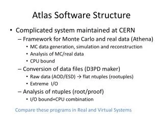
1 / 32
320 likes | 475 Vues
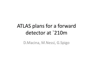
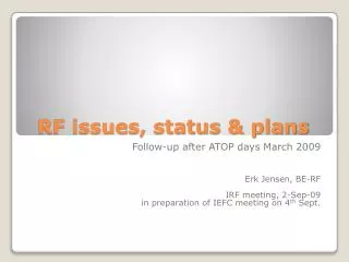
BIB's in ATLAS: Issues & Plans. W. Kozanecki (CEA-Saclay) for the ATLAS Background Working Group. Introduction: scope & scale Expected impact of Beam-Induced Backgrounds on ATLAS performance Overview of background-monitoring instrumentation What feedback could ATLAS provide?

E N D
BIB's in ATLAS: Issues & Plans W. Kozanecki (CEA-Saclay) for the ATLAS Background Working Group • Introduction: scope & scale • Expected impact of Beam-Induced Backgrounds on ATLAS performance • Overview of background-monitoring instrumentation • What feedback could ATLAS provide? • What accelerator information might prove valuable? • Special beam conditions • Summary
Scope of this Presentation • Detector-protection issues, beam-abort system & beam-accident scenarios • have so far received top priority in ATLAS • protocols are well advanced • instrumentation is installed • read-out electronics is in progress • communication & online-monitoring software in (various states of) progress These topics are considered off-subject for this meeting. • Here, focus on ‘steady-state’ machine-induced backgrounds • under ‘stable beams’ • Everything shown today • reflects the fact that in most areas the work is just starting, • is highly preliminary, and • some of it is most likely wrong!
Introduction: the Scale of the Problem • ATLAS was designed to operate efficiently @ L ~ 1034 cm-2 s-1 • At nominal LHC luminosity, particle fluxes in/around ATLAS are dominated by • p-p interaction products in the Inner Detector, calorimeters and inner layers of the muon spectrometer • a ‘sea’ of n & ’s (from high- impacts in the calorimeters & shielding) over most of the muon spectrometer • Beam-halo & beam-gas rates (both from UX & distant) need to be assessed in comparison to the above rates and occupancies • Backgrounds are likely to be worse at the beginning • relative to the actual luminosity (backgrounds scale much more slowly than L ), but also… • on an absolute scale (unconditioned vacuum system, stronger p halo) • In addition, the more open trigger may make the experiment more sensitive • On the long term (nominal currents & L ), and in view of the simulation & operational uncertainties, it would be prudent to assume that BIB's could easily end up an order of magnitude larger than predicted today. This is not done in the numbers that follow!
Expected impact on ATLAS performance (I) • Inner Detector: O (500) charged particles (from pp) per Xing (|| < 3) • Calorimeters • In most of the liquid argon calorimeters the electronics noise is roughly equal to the pileup noise at L = 1034 cm-2 s-1 • In order to be significant for event reconstruction, machine backgrounds must deposit energy density comparable to pileup events at L = 1034 cm-2 s-1 • Tile calorimeter: no quantitative study yet, but expect conclusions similar to those in LAr • Forward calorimeters: at L = 1034 cm-2 s-1, pp interactions deposit about 7 TeV/crossing on each side • in comparison, beam halo and beam-gas negligible in terms of dose & occupancy • track quality cuts eliminate most beam-gas and all halo "tracks" in ID (simulations by VT/AS)
Expected impact on ATLAS performance (II) • Trigger: see M. Huhtinen's talk • Low beam-gas rates from UX imply these are not an issue • Uncertainty in halo (and distant beam-gas) rates imply that more study is warranted on events in the tail of the distribution, and on possible muon showering effects (see MH's talk) • Overall, no indications so far of any serious trigger worries from beam backgrounds • Muon spectrometer • the fluxes of halo/beam-gas muons & of neutrons (from TCT) appears small compared to those from p-p interactions (next slide) • it might be wise to measure them at some stage (possible using a specially-configured forward- trigger; measurement may be limited to || > 1.8) • however, care needs to be exercized (at least initially) in turning on those chambers closest to the beam line
Halo + distant beam-gas predictions (pT > 10 GeV/c), assuming TCT ~ 2 106/s , L ~ 1034 R ~ 4 m: ~ 10-3 - 10-2 cm-2 s-1 R ~ 1 m: ~ 0.5 - 1 cm-2 s-1 Average expected single-plane counting rates in Hz/cm2from pp interactions at 1034 cm−2 s−1, for various regions in the muon spectrometer Even if the steady-state halo & beam gas muon rate were 10x higher than predicted, the impact on the muon spectrometer is not expected to be an issue. A preliminary estimate (VT) of the n flux is ~ 0.8 n into the ATLAS cavern, per proton incident on the TCT - not an issue.
Overview of background monitoring instrumentation • Set 1: beam conditions facing the Inner Detector • Beam Conditions Monitor (BCM) • Beam Loss Monitors (BLM) • Set 2: ATLAS subdetectors as background monitors • Trigger-like observables • Occupancy-like observables • Set 3: analyze hadron / n / fluxes, validate dose models • Radiation Monitors (ionizing-dose & neutron counters) • Neutron & photon monitors (muon spectrometer) • MediPix detectors Unlikely to be relevant to today's discussion
Time difference Beam Conditions Monitor (BCM) • Distinguish collisions from background through time-of-flight measurement with detectors at either side of the IP • 4 BCM stations on each side of the Pixel detector • mounted on Pixel support structure at z = +/- 183.8 cm and r = 6 cm • Measure # particles /cm2 for every bunchcrossing (25ns) • fast, rad-hard 1cm2 pCVD diamond sensor • fast elx (rise time ~ 1ns, width ~ 3ns, baseline restored in < 10ns) • FPGA-based control & monitoring • generates warning signals DSS • generates 2 redundant beam-abort signals ATLAS BIS • trigger signals to Central Trigger Processor (9) with hit pattern info • internal data buffer written to DCS after abort Interactions: Dt = 0, 25, … ns Upstream background: Dt = 2z/c = 12ns
BCM: t(Side A) - t(Side C) BLM's Beam Loss Monitors (BLMs) • Purpose: measure beam losses close to beam pipe by measuring the “DC” current in diamonds (similar systems used by BaBar & CDF ) • Apply voltage to diamond and measure beam-induced current • Response time of the order of ~ 40s (~ 1/2 machine turn) • 6 stations on each side at ID endplate close to beam pipe (R ~ 65 mm) • Will serve as a redundant system to BCM • Likely separate inputs to ATLAS BIS • Almost identical system in production for CMS, LHCb & Alice: will allow direct comparison of measurements between 4 LHC experiments
MBTS halo trigger 0.15 < R < 0 .89 m Fwd : halo trigger (dedicated) L1 calo rate metering ATLAS as a beam-background detector: "trigger" observables Red: always on Blue: stable beams Underlined: beam 1 2
Level-1 calorimeter trigger: pre-processor rate metering • L1Calo trigger will provide unbiased tower-by-tower rate monitoring • full map covered with high granularity • configurable energy and counting-interval threshold • independent of further ATLAS trigger event selection and DAQ → diagnostics of calorimeter channels with abnormal input rates to the ATLAS Level-1 trigger → monitoring of beam conditions during physics data taking in ATLAS → interface between ATLAS and LHC control room to optimize beam conditions
TRT: occupancy, current LUCID: occupancy, counting rate Fwd chbrs: occupancies, current,halo Pixels + SCT: occupancies ATLAS as a beam-background detector: "occupancy" observables Red: always on Blue: stable beams Underlined: beam 1 2
What information could ATLAS send to the CCC? Information sent to CCC clearly needs to be concise & easy to use; but only experience will tell what is useful & what isn't. The following is a menu of what could be made available: pick & choose! • Normalized background figures of merit (BFoM's) • present thinking: some combination of • BCM rate and/or pattern, MBTS halo-trigger rate, Lucid out-of-time rate (these distinguish beams 1 & 2 by timing; always on) • BLM dose rate, L1 calo rate metering (no timing info, but beams 1 & 2 might be distinguishable by their spatial pattern; always on) • to be clarified • which of the above signal(s) or combinations ? (needs simulations) • how to subtract the L contribution ? • how many signals are desired? if only 2, have to choose between • beam 1 + beam 2 (1 signal ea.) • 2 complementary signals that mix beams 1 & 2 • normalisation: beam-current normalized? 'pain' normalized? different normalisation during injection, ramp/squeeze, setup, physics? The choice & meaning of the BFoM's will unavoidably evolve with time - at least in ACR. What CCC 'sees' (after normalization) should remain operationally equivalent.
What information could ATLAS send to the CCC? (II) • General info • luminosity • position, orientation (?) & size of luminous region • An ATLAS 'background status' or 'beam conditions' page? • possible interface • Web page? • mirror of (well chosen) on-line monitoring display(s) ? • contents: summary background display (numbers? thermometers?) • BCM & BLM (rates, patterns for beams 1, 2) • Trigger-like observables • Minimum-bias trigger scintillators (MBTS): halo rates in ID for beams 1, 2 • L1 trigger: unbiased rate monitoring in calorimeters • muon-halo trigger & reconstruction using forward chambers (beams 1,2) • Occupancy-like observables • LUCID: background rate very close to the beam pipe (beams 1, 2) • current in TRT • forward chambers (beams 1, 2 ?) • occupancies in ID (pixel, TRT, SCT) • occupancies in forward muon chambers (beams 1, 2 ?)
What information could ATLAS send to the CCC? (III) • Bunch-by-bunch information ( - ed over many turns; scale: 0.5 -1 min) • bunch timing wrt clock from BPTX pickups (beams 1, 2) • relative bunch luminosity Lb (or specific luminosity Lsp = Lb / Ib1 Ib2) • from LUCID (2 ns time resolution, bunch-by-bunch counters exist) • backgrounds, separately for beams 1, 2 • BCM • MBTS (via bunch-by-bunch monitoring of trigger inputs in level-1 central trigger processor ) • LUCID (idem) • backgrounds (global) • L1 calo rate metering • ID and/or muon chamber occupancies? For both of these: • no 1-2 discrimination, except maybe through patterns • bunch-by-bunch capability to be confirmed
What accelerator information might prove valuable to ATLAS? • General machine parameters at point 1 The list stored on the LEADE page:https://twiki.cern.ch/twiki/bin/view/Leade/WebHome seems fairly complete. Some additional suggestions follow (next slide).
What accelerator information might prove valuable to ATLAS? (II) • General machine parameters (additional) • beam lifetimes • beam positions & angles at IP: (x, x', y', y')1,2 from beam orbit monitors • Vacuum • pump/gauge readings in incoming straights • Collimation & beam losses • jaw settings & beam-loss rates at • tertiary collimators! • betatron & momentum cleaning collimators (stage 1? stage 2?) • injection collimators? • [dump collimators?] • Beam loss monitors (other than collimators) ? Time scale for all these updates (secs to mins?) will be determined by how quickly things change: tbd on a case-by-case basis Don't be shy about sending us info you think is useful!
Undesirable beam conditions? • Rule-of-thumb: • slow time variations are OK, spikes &hickups are BAD! • prefer L to be as uniform as possible, along the bunch train & over time, so that trigger thresholds remain optimum throughout and dead-time corrections are simpler • How much is acceptable in terms of • bunch-to-bunch L variations: 20% ? (needs further study) • luminosity & background variations within a fill: that's life… • fill-to-fill luminosity & background variations: more constant = more convenience, fewer setup errors, smaller corrections • bad vacuum conditions in IR:at least 1 order of magnitude compared to current predictions [LHC project report 783] at full L • satellite bunches & particles between RF buckets • may affect baseline (pileup) subtraction • L contribution should be << systematic error on relative-L measurement (% level) • few % of charge should be safe
Special beam conditions in early running • Unpaired bunches for background monitoring ? Preliminary answer: • proved useful in CDF ? • should be available in both beams (separate background contributions) • to be worked out: • timing details (minimum gap required, where in the bunch train) • how many, how often • Displaced collisions • potentially useful for ID alignment with tracks • some (aka 'weak") deformation modes (e.g. global scale) cannot be identified/corrected using projective tracks, but can (in principle) be recovered using displaced vertices • preliminary studies show that events originating at 37.5 cm can be reconstructed with almost full efficiency • their effectiveness in improving the ID alignment remains to be quantified • 1-bucket offset (z = 37.5 cm) preferred (pixel barrel is ~ 77 cm long); 12 h of running should suffice (limit is DAQ bandwidth, not L )
Areas where work is needed before first beams (a partial list…) • Self-consistent, validated accelerator-background simulation (distant beam-gas + halo from tertiary collimators) • Background simulations in ATLAS • complex simulation machinery now ready (A. Stradling, V. Talanov) • usable by all ATLAS subdetectors - but manpower needed! • needs reference input data set: & hadrons at z = 23 m scoring plane • top priority: "calibrate" the background monitors: • BCM rate, multiplicity & patterns • BLM & MBTS signatures against particle fluxes & danger levels in • pixels, SCT, TRT • innermost forward chambers • determine how useful background muons can be to align • the Inner Detector • the muon spectrometer
Areas where work is needed before first beams (II) • Information transfer between ATLAS & LHC • top priority: • background info from ACR CCC • choose signals, choose normalization • this requires the above-mentioned simulations • ACR: comprehensive & integrated set of background monitoring tools • both ways (ACR CCC) : finalize/commission communication protocols • Background monitoring instrumentation • tool needed to monitor the backgrounds… • at large radius in the spectrometer • implementation must be completed (path is known) for monitoring • very close to the beam pipe (LUCID) • close to the pixels (BCM) • over the ID (BLM's, MBTS) • in the calorimeter (L1 rate)
Conclusions • Simulations suggest that beam-induced backgrounds should not be a major issue for ATLAS; reality, however, may decide otherwise - especially during early running • A panoply of background monitors is available • sensitive to very different time scales (1 bunch Xing to 1 ring turn), • covering from the immediate vicinity of the beam pipe to the radius of the calorimeters, and in many cases always active (including during injection). • However the halo at large radius (R > 1 m) remains difficult/cumbersome to characterize experimentally. • The definition, and the implementation, of normalized BFoM's still is at a very early stage. Progress requires • an agreed-upon set of machine simulations (exclusive rather than weighted) • identifying suficient manpower in ATLAS • Preliminary proposals have been presented with respect to • information flow from LHC to ATLAS (& v-v) • special and/or undesirable beam conditions during early running
Credits & acknowledgements • The material shown above is a modest attempt at summarizing the discussions that started two months ago in the ATLAS Background Working Group: W. Bell, D. Berge, A. Brandt, K. Einsweiler, R. Goncalo, P. Grafstrom, V. Hedberg, T. Kawamoto, R. Kwee, T. Lecompte, G. Mikenberg, M. Mikuz, G. Mornacchi, T. Pauly, J. Rutherfoord, J. Schieck, M. Shupe, A. Stradling, V. Talanov, W. Trischuk, T. Wengler, S. Wenig, and M. Wessels. N. Ellis, M. Huhtinen, J. Schieck, and C. Young also contributed directly to this presentation. • There was no way, in the time imparted, to do justice to the efforts of the teams - and of the individuals - who built, simulated, tested, installed and commissioned the various components of the ATLAS background-related instrumentation (detector protection system, BIS, BCM, BLMs, radiation & dose monitors, MBTS,…)
Expected dose distribution in ATLAS Total ionising dose per year (L = 1034 cm-2s-1) calculated by GCALOR in one quarter of the central part of the detector. The locations of the inner detector sub-systems, of the different calorimeters and of the inner end-cap muon stations are indicated. The scale on the left gives the integrated dose per year corresponding to the various isolines.
Noise/channel in ATLAS calorimeters
Particle fluxes from pp interactions, in the various muon stations at L = 1034 cm−2 s−1 as predicted by GCALOR. The neutron & photon fluxes are in kHz/cm2, the muon & proton fluxes in Hz/cm2. : 0.5 Hz/cm2 : 9Hz/cm2
The BCM is installed in ATLAS • 4 BCM stations on each side of the Pixel detector • Mounted on Pixel support structure at z = +/- 183.8 cm and r = 5.5 cm • Each station: 1cm2 detector element + Front-end analog readout
Trigger-like background observables from ATLAS: comments • MBTS • halo trigger relatively easy to impelement (may require some NIM elx) • distinguishes muons from beam 1 and from beam 2 through coincidence timing • timing distribution could be made available • Forward- halo trigger: • on the outgoing side: "easy" (although a dedicated configuration, incompatible with standard running) • two-side trigger (A-C) may be possible (no consensus…), but hard & invasive
Displaced Collisions for Alignment some systematic deformations of ID leave c2from tracks from IP unchanged e.g. inflation along the beam pipe no sensitivity for track-based alignment different track topology help to gain important additional information Tracks from displaced collisions break degeneracy