Download
1 / 38
400 likes | 645 Vues
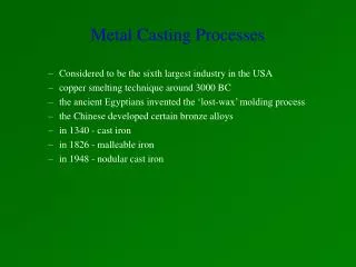
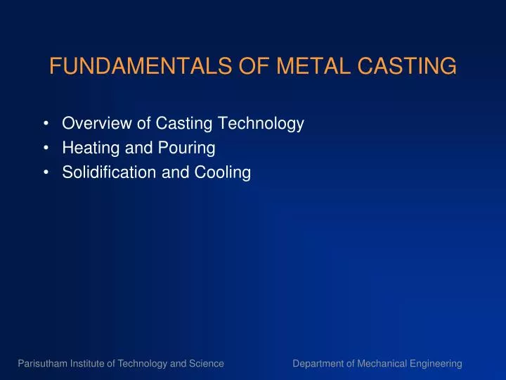
FUNDAMENTALS OF METAL CASTING. Overview of Casting Technology Heating and Pouring Solidification and Cooling. Solidification Processes. Starting work material is either a liquid or is in a highly plastic condition, and a part is created through solidification of the material

E N D
FUNDAMENTALS OF METAL CASTING • Overview of Casting Technology • Heating and Pouring • Solidification and Cooling Parisutham Institute of Technology and Science Department of Mechanical Engineering
Solidification Processes Starting work material is either a liquid or is in a highly plastic condition, and a part is created through solidification of the material • Solidification processes can be classified according to engineering material processed: • Metals • Ceramics, specifically glasses • Polymers and polymer matrix composites (PMCs) Parisutham Institute of Technology and Science Department of Mechanical Engineering
Figure 1.1 - Classification of solidification processes Parisutham Institute of Technology and Science Department of Mechanical Engineering ”
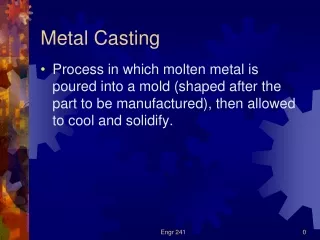
Casting Process in which molten metal flows by gravity or other force into a mold where it solidifies in the shape of the mold cavity • The term casting also applies to the part made in the process • Steps in casting seem simple: • Melt the metal • Pour it into a mold • Let it freeze Parisutham Institute of Technology and Science Department of Mechanical Engineering
Capabilities and Advantages of Casting • Can create complex part geometries • Can create both external and internal shapes • Some casting processes are net shape; others are near net shape • Can produce very large parts • Some casting methods are suited to mass production Parisutham Institute of Technology and Science Department of Mechanical Engineering
Disadvantages of Casting • Different disadvantages for different casting processes: • Limitations on mechanical properties • Poor dimensional accuracy and surface finish for some processes; e.g., sand casting • Safety hazards to workers due to hot molten metals • Environmental problems Parisutham Institute of Technology and Science Department of Mechanical Engineering ”
Parts Made by Casting • Big parts: engine blocks and heads for automotive vehicles, wood burning stoves, machine frames, railway wheels, pipes, church bells, big statues, and pump housings • Small parts: dental crowns, jewelry, small statues, and frying pans • All varieties of metals can be cast, ferrous and nonferrous Parisutham Institute of Technology and Science Department of Mechanical Engineering
Overview of Casting Technology • Casting is usually performed in a foundry Foundry = factory equipped for making molds, melting and handling molten metal, performing the casting process, and cleaning the finished casting • Workers who perform casting are called foundrymen Parisutham Institute of Technology and Science Department of Mechanical Engineering
The Mold in Casting • Contains cavity whose geometry determines part shape • Actual size and shape of cavity must be slightly oversized to allow for shrinkage of metal during solidification and cooling • Molds are made of a variety of materials, including sand, plaster, ceramic, and metal Parisutham Institute of Technology and Science Department of Mechanical Engineering ”
Figure 10.2 ‑ Two forms of mold: (a) open mold, simply a container in the shape of the desired part; and (b) closed mold, in which the mold geometry is more complex and requires a gating system (passageway) leading into the cavity Parisutham Institute of Technology and Science Department of Mechanical Engineering
Two Categories of Casting Process • Expendable mold processes – uses an expendable mold which must be destroyed to remove casting • Mold materials: sand, plaster, and similar materials, plus binders • Permanent mold processes – uses a permanent mold which can be used many times to produce many castings • Made of metal (or, less commonly, a ceramic refractory material Parisutham Institute of Technology and Science Department of Mechanical Engineering ”
Advantages and Disadvantages • More intricate geometries are possible with expendable mold processes • Part shapes in permanent mold processes are limited by the need to open mold • Permanent mold processes are more economic in high production operations Parisutham Institute of Technology and Science Department of Mechanical Engineering
Figure 10.2 (b) Sand casting mold Parisutham Institute of Technology and Science Department of Mechanical Engineering
Sand Casting Mold Terms • Mold consists of two halves: • Cope = upper half of mold • Drag = bottom half • Mold halves are contained in a box, called a flask • The two halves separate at the parting line Parisutham Institute of Technology and Science Department of Mechanical Engineering
Forming the Mold Cavity • Mold cavity is formed by packing sand around a pattern, which has the shape of the part • When the pattern is removed, the remaining cavity has desired shape of cast part • The pattern is usually oversized to allow for shrinkage of metal as it solidifies and cools • Sand for the mold is moist and contains a binder to maintain shape Parisutham Institute of Technology and Science Department of Mechanical Engineering
Cores in the Mold Cavity • The mold cavity provides the external surfaces of the cast part • In addition, a casting may have internal surfaces, determined by a core, placed inside the mold cavity to define the interior geometry of part • In sand casting, cores are generally made of sand Parisutham Institute of Technology and Science Department of Mechanical Engineering
Gating System Channel through which molten metal flows into cavity from outside of mold • Consists of a downsprue, through which metal enters a runner leading to the main cavity • At top of downsprue, a pouring cup is often used to minimize splash and turbulence as the metal flows into downsprue Parisutham Institute of Technology and Science Department of Mechanical Engineering
Riser Reservoir in the mold which is a source of liquid metal to compensate for shrinkage during solidification • The riser must be designed to freeze after the main casting in order to satisfy its function Parisutham Institute of Technology and Science Department of Mechanical Engineering ”
Heating the Metal • Heating furnaces are used to heat the metal to molten temperature sufficient for casting • The heat required is the sum of: • Heat to raise temperature to melting point • Heat of fusion to convert from solid to liquid • Heat to raise molten metal to desired temperature for pouring Parisutham Institute of Technology and Science Department of Mechanical Engineering ”
Pouring the Molten Metal • For this step to be successful, metal must flow into all regions of the mold, most importantly the main cavity, before solidifying • Factors that determine success: • Pouring temperature • Pouring rate • Turbulence Parisutham Institute of Technology and Science Department of Mechanical Engineering ”
Solidification of Metals Transformation of molten metal back into solid state • Solidification differs depending on whether the metal is a pure element or an alloy Parisutham Institute of Technology and Science Department of Mechanical Engineering
A pure metal solidifies at a constant temperature equal to its freezing point (same as melting point) Figure 10.4 ‑ Cooling curve for a pure metal during casting Parisutham Institute of Technology and Science Department of Mechanical Engineering
Solidification of Pure Metals • Due to chilling action of mold wall, a thin skin of solid metal is formed at the interface immediately after pouring • Skin thickness increases to form a shell around the molten metal as solidification progresses • Rate of freezing depends on heat transfer into mold, as well as thermal properties of the metal Parisutham Institute of Technology and Science Department of Mechanical Engineering ”
Figure 10.5 ‑ Characteristic grain structure in a casting of a pure metal, showing randomly oriented grains of small size near the mold wall, and large columnar grains oriented toward the center of the casting Parisutham Institute of Technology and Science Department of Mechanical Engineering
Most alloys freeze over a temperature range rather than at a single temperature Figure 10.6 ‑ (a) Phase diagram for a copper‑nickel alloy system and (b) associated cooling curve for a 50%Ni‑50%Cu composition during casting Parisutham Institute of Technology and Science Department of Mechanical Engineering
Figure 10.7 ‑ Characteristic grain structure in an alloy casting, showing segregation of alloying components in center of casting Parisutham Institute of Technology and ScienceParisutham Institute of Technology and Science Department of Mechanical Engineering
Solidification Time • Solidification takes time • Total solidification time TST = time required for casting to solidify after pouring • TST depends on size and shape of casting by relationship known as Chvorinov's Rule Parisutham Institute of Technology and Science Department of Mechanical Engineering
Chvorinov's Rule where TST = total solidification time; V = volume of the casting; A = surface area of casting; n = exponent usually taken to have a value = 2; and Cm is moldconstant Parisutham Institute of Technology and Science Department of Mechanical Engineering
Mold Constant in Chvorinov's Rule • Cm depends on mold material, thermal properties of casting metal, and pouring temperature relative to melting point • Value of Cm for a given casting operation can be based on experimental data from previous operations carried out using same mold material, metal, and pouring temperature, even though the shape of the part may be quite different Parisutham Institute of Technology and Science Department of Mechanical Engineering
What Chvorinov's Rule Tells Us • A casting with a higher volume‑to‑surface area ratio cools and solidifies more slowly than one with a lower ratio • To feed molten metal to main cavity, TST for riser must greater than TST for main casting • Since riser and casting mold constants will be equal, design the riser to have a larger volume‑to‑area ratio so that the main casting solidifies first • This minimizes the effects of shrinkage Parisutham Institute of Technology and Science Department of Mechanical Engineering
Figure 10.8 ‑ Shrinkage of a cylindrical casting during solidification and cooling: (0) starting level of molten metal immediately after pouring; (1) reduction in level caused by liquid contraction during cooling (dimensional reductions are exaggerated for clarity in sketches) Parisutham Institute of Technology and Science Department of Mechanical Engineering
Figure 10.8 ‑ (2) reduction in height and formation of shrinkage cavity caused by solidification shrinkage; (3) further reduction in height and diameter due to thermal contraction during cooling of the solid metal (dimensional reductions are exaggerated for clarity in our sketches) Parisutham Institute of Technology and Science Department of Mechanical Engineering
Solidification Shrinkage • Occurs in nearly all metals because the solid phase has a higher density than the liquid phase • Thus, solidification causes a reduction in volume per unit weight of metal • Exception: cast iron with high C content • Graphitization during final stages of freezing causes expansion that counteracts volumetric decrease associated with phase change Parisutham Institute of Technology and Science Department of Mechanical Engineering
Shrinkage Allowance • Patternmakers account for solidification shrinkage and thermal contraction by making mold cavity oversized • Amount by which mold is made larger relative to final casting size is called pattern shrinkage allowance • Casting dimensions are expressed linearly, so allowances are applied accordingly Parisutham Institute of Technology and Science Department of Mechanical Engineering
Directional Solidification • To minimize damaging effects of shrinkage, it is desirable for regions of the casting most distant from the liquid metal supply to freeze first and for solidification to progress from these remote regions toward the riser(s) • Thus, molten metal is continually available from risers to prevent shrinkage voids • The term directionalsolidification describes this aspect of freezing and methods by which it is controlled Parisutham Institute of Technology and Science Department of Mechanical Engineering
Achieving Directional Solidification • Desired directional solidification is achieved using Chvorinov's Rule to design the casting itself, its orientation in the mold, and the riser system that feeds it • Locate sections of the casting with lower V/A ratios away from riser, so freezing occurs first in these regions, and the liquid metal supply for the rest of the casting remains open • Chills ‑ internal or external heat sinks that cause rapid freezing in certain regions of the casting Parisutham Institute of Technology and Science Department of Mechanical Engineering
Figure 10.9 ‑ (a) External chill to encourage rapid freezing of the molten metal in a thin section of the casting; and (b) the likely result if the external chill were not used Parisutham Institute of Technology and Science Department of Mechanical Engineering
Riser Design • Riser is waste metal that is separated from the casting and remelted to make more castings • To minimize waste in the unit operation, it is desirable for the volume of metal in the riser to be a minimum • Since the geometry of the riser is normally selected to maximize the V/A ratio, this allows reduction of riser volume as much as possible Parisutham Institute of Technology and Science Department of Mechanical Engineering