Download
1 / 4
40 likes | 276 Vues
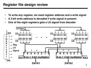
IN3. IN2. IN1. IN0. D0. D1. D2. D0. MUX. MUX. MUX. MUX. LD. LD. LD. LD. D. Q. D. Q. D. Q. D. Q. Q3. Q2. Q1. Q0. C. C. C. C. Clock. A register design with parallel load input. Flip-flops can be connected to act as a register

E N D
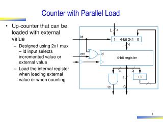
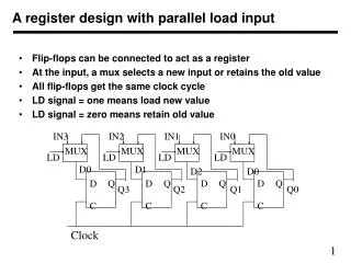
IN3 IN2 IN1 IN0 D0 D1 D2 D0 MUX MUX MUX MUX LD LD LD LD D Q D Q D Q D Q Q3 Q2 Q1 Q0 C C C C Clock A register design with parallel load input • Flip-flops can be connected to act as a register • At the input, a mux selects a new input or retains the old value • All flip-flops get the same clock cycle • LD signal = one means load new value • LD signal = zero means retain old value
IN23 IN22 IN21 IN20 IN13 IN12 IN11 IN10 4-Bit Register 4-Bit Register LD1 LD2 Clock Clock Q13 Q12 Q11 Q10 Q23 Q22 Q21 Q20 Sel MUX MUX MUX MUX Multiple registers • In a system we can have more than one register • For an operation we can select any of the registers • Each register can be loaded or old value can be retained • A register can be selected for output • There can be more than one set of multiplexers at the output
LD1 M1 OpCode 4-bit Reg M U X A L U 4-bit Reg M U X LD2 M2 Connecting registers to ALU • A set of registers with selection signals can produce two outputs • These outputs can be connected to ALU input • A 4-function ALU receives two inputs and produces one output • It needs two select bits to selects function • Needs LD1, and LD2 signals, M1 and M2 signal
Keyboard LD1 M1 OpCode 4-bit Reg M U X enable enable A L U 4-bit Reg M U X LD2 M2 Writing result back to registers • Output of ALU may have to be written in registers • Registers may also get data from somewhere else like keyboard • Therefore we need to select data to be written to register file • This requires another multiplexer • Or we can use a bus