Download
1 / 30
300 likes | 400 Vues
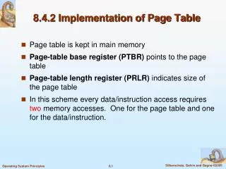
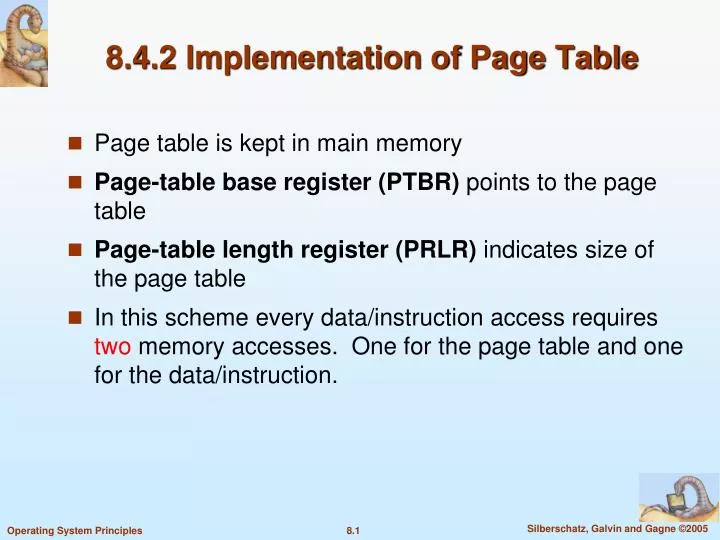
8.4.2 Implementation of Page Table. Page table is kept in main memory Page-table base register (PTBR) points to the page table Page-table length register (PRLR) indicates size of the page table

E N D
8.4.2 Implementation of Page Table • Page table is kept in main memory • Page-table base register (PTBR) points to the page table • Page-table length register (PRLR) indicates size of the page table • In this scheme every data/instruction access requires two memory accesses. One for the page table and one for the data/instruction.
Implementation of Page Table • The two memory access problem can be solved by the use of a special fast-lookup hardware cache called associative (組合) memory or translation look-aside buffers (TLBs) • Some TLB allow certain entries to be wired down, meaning that they cannot be removed from the TLB. • Typically TLB entries for kernel code are wired down. • Some TLBs store address-space identifiers (ASIDs) in each TLB entry – uniquely identifies each process to provide address-space protection for that process • Typically, the number of entries in a TLB is small, often between 64 and 1024
Associative Memory • Associative memory – parallel search Address translation (p, d) • If p is in associative register, get frame # out • Otherwise get frame # from page table in memory Page # Frame #
Effective Access Time Example • Associative Lookup = 20 nanoseconds • Assume memory cycle time is 100 nanoseconds • Hit ratio – percentage of times (次數) that a page number is found in the associative registers; ratio related to number of associative registers • Let Hit ratio = • Effective Access Time(EAT) EAT = (100 + 20)* + (200 + 20)(1 – ) = 220 – 100 *
Memory Protection • Memory protection implemented by associating protection bits with each frame. • For example, one bit can define a page to be read-write or read-only. • The approach could be expanded to a finer level of protection • Valid-invalid bit attached to each entry in the page table: • “valid” indicates that the associated page is in the process’ logical address space, and is thus a legal page • “invalid” indicates that the page is not in the process’ logical address space
Valid (v) or Invalid (i) Bit In A Page Table A program with logical addresses 0 to 10468. Note that a logical address of 10568 is ‘valid’, but it will be blocked by limit register.
Shared Pages • Shared code • One copy of read-only (reentrant) code shared among processes (i.e., text editors, compilers, window systems). • Shared code must appear in same location in the logical address space of all processes • Private code and data • Each process keeps a separate copy of the code and data • The pages for the private code and data can appear anywhere in the logical address space
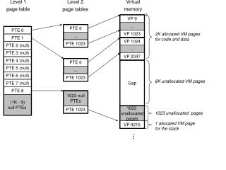
8.5 Structure of the Page Table • Hierarchical Paging • Break up the logical address space into multiple page tables • A simple technique is a two-level page table, in which the page table itself is also paged page number page offset p2 p1 d 10 10 12 where p1 is an index into the outer page table, and p2 is the displacement within the page of the outer page table
Two-Level Paging Example • A logical address (on 32-bit machine with 4K page size) is divided into: • a page number consisting of 20 bits • a page offset consisting of 12 bits • Since the page table is paged, the page number is further divided into: • a 10-bit page number • a 10-bit page offset of the outer pager table
Address-Translation Scheme Since address translation works from outer page table inward, it is also known as forward-mapped page table.
Three-level Paging Scheme For a system with 64-bit logical address space, the following should be avoided: Too many levels would require too many number of memory accesses To translate each logical address.
Hashed Page Tables • Common in address spaces > 32 bits • The virtual page number is hashed into a page table. This page table contains a chain of elements hashing to the same location. • Virtual page numbers are compared in this chain searching for a match. If a match is found, the corresponding physical frame is extracted. • A variation uses cluster page tables, where each entry in the hash table refers to several pages (such as 16) rather than a single page
Inverted Page Table • One entry for each real page of memory • Need only one inverted page table in a system • Entry consists of the virtual address of the page stored in that real memory location, with information about the process that owns that page • Decreases memory needed to store each page table, but increases time needed to search the table when a page reference occurs • Use hash table to limit the search to one — or at most a few — page-table entries • Hard to implement shared memory
8.6 Segmentation • Memory-management scheme that supports user view of memory • A program is a collection of segments. A segment is a logical unit such as: main program, procedure, function, method, object, local variables, global variables, common block, stack, symbol table, arrays
1 4 2 3 Logical View of Segmentation 1 2 3 4 user space physical memory space
Segmentation Architecture • A logical address consists of a two tuple: <segment-number, offset> • Segment table – maps two-dimensional physical addresses; each table entry has: • base – contains the starting physical address where the segments reside in memory • limit – specifies the length of the segment • Segment-table base register (STBR) points to the segment table’s location in memory • Segment-table length register (STLR) indicates number of segments used by a program; • a segment number s is legal if s < STLR
Segmentation Architecture • Protection • With each entry in segment table associate: • validation bit = 0 illegal segment • read/write/execute privileges • Protection bits associated with segments; code sharing occurs at segment level • Since segments vary in length, memory allocation is a dynamic storage-allocation problem • A segmentation example is shown in the following diagram
8.7 Example: The Intel Pentium • Supports both segmentation and segmentation with paging • CPU generates logical address • Given to segmentation unit • Which produces linear addresses • Linear address given to paging unit • Which generates physical address in main memory • Paging units form equivalent of MMU
Logical to Physical Address Translation in Pentium segment number LDT/GDT protection g s offset p 1 32 2 13 LDT: local descriptor table GDT: global descriptor table Each entry in LDT or GDT has 8-byte segment descriptor with detailed information about the segment, including the base location and limit of that segment
Pentium Paging Architecture skip 8.7.3
8.8 Summary • The following considerations are used in comparing different memory management strategies: • Hardware support • Performance • Fragmentation • Relocation • Swapping • Sharing • Protection