Download
1 / 13
200 likes | 497 Vues
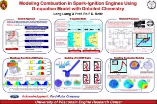
Air-Fuel Ratio Control in Spark-Ignition Engines. Presented to: Dr. Riadh Habash, Fouad F. Khalil Presented by: Ziad El Kayal, Hassan Fakih Umar Qureshi, Marc Topalian. How it Works. Air and the fuel enter the carburetor, then through the engine and finally past a senor

E N D
Air-Fuel Ratio Control in Spark-Ignition Engines Presented to: Dr. Riadh Habash, Fouad F. Khalil Presented by: Ziad El Kayal, Hassan Fakih Umar Qureshi, Marc Topalian
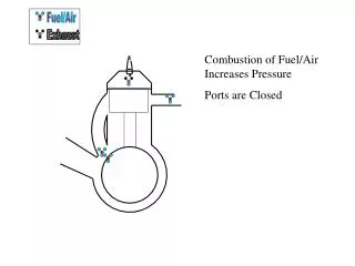
How it Works • Air and the fuel enter the carburetor, then through the engine and finally past a senor • Using a sensor to measure the oxygen content of the engine's exhaust, the system keeps the fuel-air ratio very close to the proportion for chemically perfect combustion
References • “Air-Fuel Ratio Control in Spark-Ignition Engines Using Estimation Theory” Chen-Fang Chang, Nicholas P. Fekete, AloisAmstutz, and J. David Powell • “Development of a Transient Air Fuel Controller for an Internal Combustion Engine” Stewart P. Prince • “Digital Control of an Automobile Engine Air-Fuel Ratio System” Martin J. Dubois, Robert P. Van Til, Nicholas G. Zorka • “Individual Cylinder Air-Fuel Ratio Control with a Single EGO Sensor” Jessy W. Grizzle, Kelvin L. Dobbins, and Jeffrey A. Cook • “Design and Development of an ECU and its Air-Fuel Ratio Control Scheme” Myomgho Sunwoo, Hansub Sim andKangyune Lee
Requirements • The controller must keep a fuel to air ratio of 1:14.7 (0.068) • The overshoot at the output must not be greater than 16%. • The settling time must be less than or equal to 10 seconds.
Required Characteristic Equation • From the IEEE article, the maximum overshoot required is 16% and the maximum settling time was 10 seconds. • Required Characteristic Equation: • s2 + 2wnζs + 2wn • Through calculation we found • ζ (damping factor) = 0.5 • wn=0.8 rad/s • Therefore, set s equal to zero and find the poles, using the quadratic equation: • s1=-0.4 + 0.4√3 i • s2=-0.4 - 0.4√3 i
Open Loop Transfer Function • We needed to find a transfer function we could use to plot a root locus diagram • We found the open loop transfer function of our block diagram to get the following formula (0.5t2Td + 0.5t1Td)s + Td T1t2s2 + (t1 + t2)s + 1 • Using constants from IEEE references we were able to plot the following root locus diagram • The diagram allowed us to find the roots and poles of the transfer function • From the diagram we were able to design the lead compensator
Design of Lead Compensator • Required Formula Gc(s)= (s+z) / (s+p) • The zero is found from the previous calculations, z = 0.4 • Use Root Locus method to find the value of the pole. • Draw straight lines from s1 to all the poles and zeros found on the root locus • No need to use s2 because it is just a complex conjugate • Find the angle at which the pole is located ∂1= 177 degrees ∂2= 50 degrees) ∂3= 5 degrees) ∂4= 1 degree ∂ = 19 degrees Using +∂ -∂1 -∂2 -∂3 -∂4 -∂d=-180 degrees ∂d=65 degrees • Using this we were able to find the pole which we used to design our lead compensator Gc(s)= (s+0.4) / (s+0.6)
Conclusion • Through research, we were able to design a controller to regulate the fuel to air ration in a spark-ignition engine with an overshoot of 11% and a settling time of 10 seconds. • We were able to accomplish the emission standards by adjusting the fuel to air ratio required by the IEEE paper.