Download
1 / 17
280 likes | 1.91k Vues
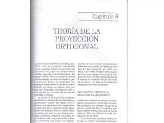
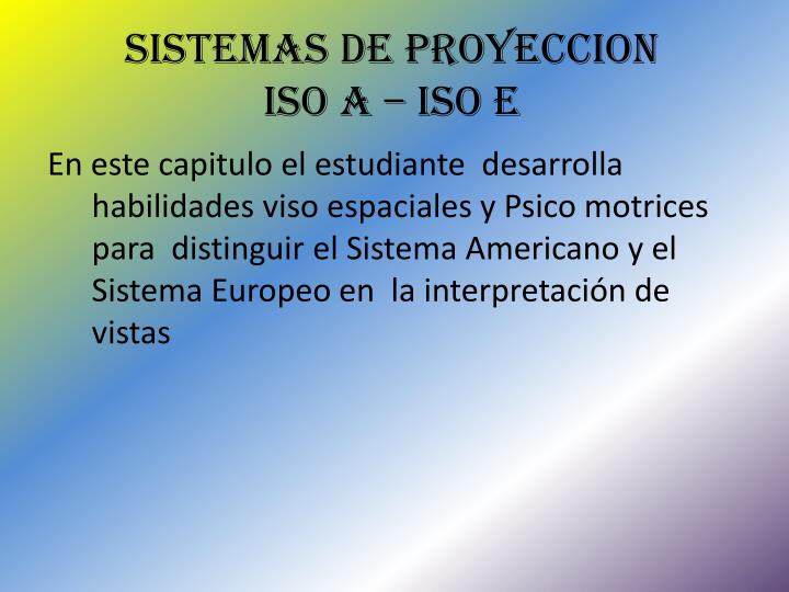
SISTEMAS DE PROYECCION ISO A – ISO E. En este capitulo el estudiante desarrolla habilidades viso espaciales y Psico motrices para distinguir el Sistema Americano y el Sistema Europeo en la interpretación de vistas. ESCUELA TECNOLOGICA ITC CURSO ON LINE GEOMETRIA DESCRPITIVA 2014.

E N D
SISTEMAS DE PROYECCION ISO A – ISO E En este capitulo el estudiante desarrolla habilidades viso espaciales y Psico motrices para distinguir el Sistema Americano y el Sistema Europeo en la interpretación de vistas
ESCUELA TECNOLOGICA ITCCURSO ON LINE GEOMETRIA DESCRPITIVA2014 NORMA TECNICA COLOMBIANA NTC 1777
POSICION DE LOS SISTEMAS EN EL ANGULO DIEDRO • En el 1° cuadrante se localiza la Norma Europea Iso E o DIN • En el 2° cuadrante se localiza la Norma Americana Iso A o ASA
METODO DE PROYECCION DEL PRIMER ANGULO ISO E (DIN) • POSICION DEL PLANO DE PROYECCION NORMA EUROPEA ALEMANA UBICADA EN EL PRIMER CUADRANTE DEL ANGULO DIEDRO Y CUYA POSICION DE LOS CUATRO ELEMENTOS SON: 1.OBSERVADOR2.OBJETO 3.PLANO DE PROYECCION4. LINEAS PROYECTANTES O RAYOS VISUALES OBSERVESE QUE EL PLANO DE PROYECCION ESTA UBICADO DETRAZ DEL OBSERVADOR
REPRESENTACION DE LA NORMA ISO E • SE REPRESENTA CON EL SIGUIENTE SIMBOLO PD PS HS
METODO DE PROYECCION DEL TERCER CUADRANTE ISO A (ASA) • POSICION DEL PLANO DE PROYECCION NORMA AMERICANA UBICADA EN EL TERCER CUADRANTE DEL ANGULO DIEDRO Y CUYA POSICION DE LOS CUATRO ELEMENTOS SON: 1.OBSERVADOR2.OBJETO 3.PLANO DE PROYECCION4. LINEAS PROYECTANTES O RAYOS VISUALES OBSERVESE QUE EL PLANO DE PROYECCION ESTA UBICADO ENTRE EL OBSERVADOR Y EL OBJETO
REPRESENTACION NORMA ISO A SE REPRESENTA CON EL SIGUIENTE SIMBOLO HS F PD
DESIGNACION DE LAS VISTAS • Vista en dirección a : vista de frente • Vista en dirección b : vista superior • Vista en dirección c : vista izquierda • Vista en dirección d : vista derecha • Vista en dirección e : vista inferior • Vista en dirección f : vista posterior
SELECCIÓN DE VISTAS Se debe conocer la vista que proporcione mayor información como vista de frente o principal. En general, esta vista muestra las pieza en su posición de funcionamiento, preferiblemente en la posición principal de fabricación o montaje.
Se limitara la selección de vistas y secciones al mínimo necesario y suficiente para delinear bien el objeto sin ambigüedades. • Para evitar la necesidad de contornos y aristas ocultas. • Para evitar la repetición innecesaria de detalles.
VISTAS AUXILIARES • Es necesario ver una vista desde otra dirección diferente a las indicadas anterior mente, si no se puede colocar en su posición correcta con los métodos indicados anteriormente . se usara flechas de referencia para ver la vista como corresponde.
VISTAS PARCIALES Se podrán usar las vistas parciales cuando las vistas completas no mejoran la información necesaria. La vista parcial deberá estar cortada por una línea delgada punteada o por líneas rectas en zigzag.
VISTAS LOCALES Siempre y cuando la presentación no sea ambigua, esta permitido presentar un vista local en vez de una vista completa, cuando se trata de objetos simetricos.la vista local puedes esta dibujada como proyección del tercer Angulo sin tener en cuenta la disposición del dibujo en general.
Se dibujara las vistas locales con líneas gruesas y continuas y estarán conectadas con la vista principal con una línea central. ejemplos: