Download
1 / 29
320 likes | 532 Vues
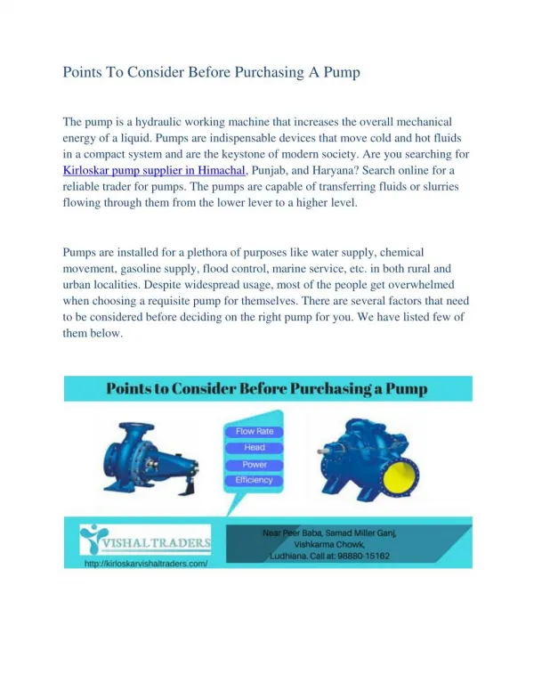
ME 388 – Applied Instrumentation Laboratory Centrifugal Pump Lab. References. Streeter and Wylie, Fluid Mechanics (Ch.10) Holman, Experimental Methods for Engineers , (Ch.6) Munson (Ch.9) Any Fluid Mechanics book. Lab Objectives. Understand operation of a dc motor

E N D
ME 388 – Applied Instrumentation LaboratoryCentrifugal Pump Lab
References • Streeter and Wylie, Fluid Mechanics (Ch.10) • Holman, Experimental Methods for Engineers, (Ch.6) • Munson (Ch.9) • Any Fluid Mechanics book
Lab Objectives • Understand operation of a dc motor • Analyze fluid flow using • Centrifugal pump • Venturi flow meter • Evaluate pump performance as a function of impeller (shaft) speed • Develop pump performance curves • Assess efficiencies
dc motor • Armature or rotor • Commutator • Brushes • Axle • Field magnet • DC power supply Figure 1. dc motor (howstuffworks.com)
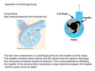
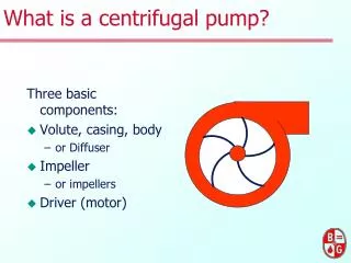
http://www.cheresources.com/centrifugalpumps1.shtml Centrifugal pump
Centrifugal pump operation • Rotating impeller delivers energy to fluid • Governing equations or Affinity Laws relate pump speed to: • Flow rate, Q • Pump head, Hp • Fluid power, P
Pump Affinity Laws • N Q • N2 Hp • N3 P
Determination of Flow Rate • Use Venturi meter to determine Q • Fluid is incompressible (const. ) • Q = Vfluid Area
Venturi Meter • As V, kinetic energy • T = 0 • Height = 0 • Pv or P
Calculate Q from Venturi data • V1 = inlet velocity • V2 = throat velocity • A1 = inlet area • A2 = throat area
Solve for Q • Use MS EXCEL (or Matlab) • Calculate throat velocity • Calculate discharge coefficient using Reynold’s number and throat velocity • Calculate throat area • Solve for Q
Power and Pump Efficiency • Assumptions • No change in elevation • No change in pipe diameter • Incompressible fluid • T = 0 • Consider 1st Law (as a rate eqn.)
Summary of Lab Requirements • Plots relating Hp, P, and pump to Q • Plot relating P to pump • Regression analyses • Uncertainty of overall (requires unc. of Q) • Compare Hp, P, Q for two N’s • For fully open valve position • WRT affinity laws
Start-up Procedure • Fill pvc tube with water (3/4 full) • Bleed pump • Switch breaker to “on” • Push main start button • Make sure variac is turned counterclockwise • Make sure throttle valve is fully open • Turn lever to “pump” • Push “reset” button • Push “start” button • Adjust variac to desired rpm using tach.
Shut-down Procedure • Fully open throttle valve • Turn variac fully counterclockwise • Push pump stop button • Turn pump lever to “off” • Push main stop button • Switch breaker to “off”