Download
1 / 67
720 likes | 872 Vues
CERN Detector Seminar. 8 February 2013. Overview of the LHCb calorimeter detectors. Pascal Perret LPC Clermont. Heavy Flavours @ LHC. High rate of background events: σ vis . Inel . ~ 60 mb at √s =7 TeV 1/200 event contains a b quark, typical interesting BR < 10 -3. TRIGGER!.

E N D
CERN Detector Seminar 8 February 2013 Overview of the LHCb calorimeter detectors Pascal Perret LPC Clermont
Heavy Flavours @ LHC • High rate of background events: • σvis. Inel. ~ 60 mb at √s =7 TeV • 1/200 event contains a b quark, typical interesting BR < 10-3 TRIGGER! Pascal Perret - LPC Clermont • LHC is a B- and D-mesons super factory: • Large bb cross section (~250 µb – 500 µb @ √s=7 – 14 TeV): • LHCb measurement @ 7 TeV[PLB 694 (2010) 209]: • ~ 280 μb (~75 ± 14 μb in LHCb acceptance) • σcc is 20 times larger! [LHCb-CONF-2010-013] σ(pp → ccX) = ~6 mb • LHCb acceptance / 1 fb-1: • ~1011 b decays [all species produced, B0,B+,BS, Λb,..] • b-hadrons produced at low angle • Spreading predominantly in the narrow cone around the beam
Outline Pascal Perret - LPC Clermont • The LHCb detector • The LHCb calorimeters • Commissioning & operation • Calibration • Stability • Performances • Conclusion
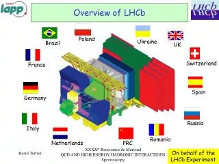
The LHCb detector ATLAS & CMS region |η|< 2.5 LHCbregion 2 < η < 5 ~10m 10 – 250 mrad 10 – 300 mrad ~20m Pascal Perret - LPC Clermont • A single-arm forwardspectrometer: • Covers ~4% of the solid angle, but captures ~30% of the heavy quark production cross-section
The LHCb detector Pascal Perret - LPC Clermont
p p The LHCb detector RICH2 TT Si Outer Tracker straw Tubes ECAL HCAL Magnet VELO&PU Si Muon MWPCGEM Inner Tracker Si RICH1 PS+SPD [The LHCb Detector at the LHC, JINST 3 (2008) S08005] Pascal Perret - LPC Clermont
The LHCbcalorimeters HCAL ECAL PS SPD Inner Outer Middle region ECAL (inner modules): σ(E)/E ~ 8.2% /√E + 0.9% • Calorimeter system : • Detection of electrons, π0, γ, hadrons • Level 0 trigger: high ETelectron and hadron, photon [JINST 3 (2008) S08005, LHCbcalorimeters", TDR, CERN/LHCC/2000-0036 LHCb TDR 2] Pascal Perret - LPC Clermont
p p The LHCb detector σ(E)/E ~ 70%/√E 10% σ(E)/E ~ 10%/√E 1% σm~90 MeV for B0K* σm~8 MeV for B+J/K+, 25 MeV for Bµ+µ- ~20 µm IP resolution at PT > 2 GeV Excellent muon identication = 97%, misid 2% (k k) 90% for (k ) <10% • Great Vertex Resolution! Primary/secondary separation, proper time resolution. • Excellent momentum and mass resolution. • Outstanding PID (K-π) and μ reconstruction. • Dedicated Trigger system for B and C! Pascal Perret - LPC Clermont
LHCb trigger Pascal Perret - LPC Clermont • Level-0 trigger: hardware • 4 μs latency @ 40MHz • “Moderate” ET/pT threshold: • Typically • ET(e/γ)>2.7 GeV • ET(h)>3.6 GeV • pT(μ)>1.4 GeV/c • HLT trigger: software • ~30000 tasks in parallel on ~1500 nodes • Storage rate: 5 kHz • Combined efficiency (L0+HLT): • ~90 % for di-muon channels • ~30 % for multi-body hadronic final states
LHCboperation LHC High Efficiency! (operation)>94% ~98% are good data! 2012 2011 Detectors all with >~99% active channels 2010 Semi-continuous (automatic) adjustment of offset of colliding beams allows luminosity to be levelled 15 h! 4x1032cm-2s-1 Design: 2x1032cm-2s-1 • 4 times more collisions per crossing than in the design!!! Pascal Perret - LPC Clermont
The LHCbcalorimeters Pascal Perret - LPC Clermont
LHCbCalorimeter System 120 mm Y~7m X~8.5m PS/SPD HCAL ECAL 60 mm 40 Z~2.7m Pascal Perret - LPC Clermont • 40 MHz trigger on energetice, π0, γ, h • Distance to i.p. ~13 m • Solid angle coverage 300x250 mrad • Four sub-detectors: SPD,PS,ECAL,HCAL • Independently retractable halves • Granularity: • SPD, PS, ECAL: • 6016 cells: 3 zones 4x4; 6x6 and 12x12 cm2 • HCAL: 1488 cells: 13x13 and 26x26 cm2
LHCbCalorimeter System Y~7m X~8.5m PS/SPD HCAL ECAL Z~2.7m Pascal Perret - LPC Clermont • 40 MHz trigger on energetice, π0, γ, h • Distance to i.p. ~13 m • Solid angle coverage 300x250 mrad • Four sub-detectors: SPD,PS,ECAL,HCAL • Independently retractable halves • Granularity: • SPD, PS, ECAL: • 6016 cells: 3 zones 4x4; 6x6 and 12x12 cm2 • HCAL: 1488 cells: 13x13 and 26x26 cm2 • Detection • Sandwich of scintillator/lead (iron for HCAL) • WLS fibres are used to collect the light read out thanks to photomultipliers (PMT) • Multianode PMT (64) for SPD & PS • Cost effective
SPD & PS Y~7m X~8.5m PS/SPD HCAL ECAL Z~2.7m Pascal Perret - LPC Clermont • Scintillator Pad Detector (SPD)and Preshower(PS) : • Particle ID for L0 electron and photon trigger • electron, photon/pion separation by PS • photon/MIP separation by SPD • Charged multiplicity by SPD • Scintillator Pad – 2.5X0lead – Scintillator Pad • 15/15/15 mm thick; • WLS fibres are used to collect the light
module 0.5x0.5m2 6016 cells 5x100 boards The Preshower 4 m 8 m + Services Pascal Perret - LPC Clermont
ECAL Y~7m X~8.5m PS/SPD HCAL ECAL Z~2.7m Pascal Perret - LPC Clermont • Electromagnetic Calorimeter (ECAL): • ETof electrons, photons and π0for L0 trigger (Bd→ K*ee, B0→ K*, etc.) • Reconstruction of π0and prompt γoffline • Particle ID • 66 layers of 2mm Pb/ 4mm scintillator • Light collected through WLS fibresbunch • Moliere radius: 3.5 cm • Longitudinal size: 25X0, 1.1 I, • Dynamic range: 10 ÷ 12 GeV of transverse energy (E(max, GeV)=7 + 10 /sin(θ)) • Energy resolution (beam tests) σ(E)/E = (8 ÷ 10)% /√E 0.9%
3312 shashlik modules with 25 X0Pb ECAL ECAL Shashlik modules Inner Module 9 cells: 4x4 cm2 Middle Module 4 cells: 6x6 cm2 Outer Module 1 cell: 12x12 cm2 Sc:Pb = 4:2 mm 25 X0 12x12 cm2 PMT and CW base Scintillators, lead-plates, covers Fibres with loops PMT Front- cover End- cover Hamamatsu R7899-20 Kuraray Y-11(250) MSJ CW base TYVEK Scintillator Lead plate Pascal Perret - LPC Clermont
HCAL Y~7m X~8.5m PS/SPD HCAL ECAL Z~2.7m Pascal Perret - LPC Clermont • HadronicCalorimeter (HCAL): • ETof hadrons, ET for L0 trigger • ~ 500 kHz (out of ~1 MHz) • 26x2 horizontal modules • The same design as in ATLAS TileCal • interleaving Sc tiles and iron plates parallel to the beam axis. Volume ratio Fe:Sc = 5.58:1 • Longitudinal size: 5.6 I • Mostly used as a trigger device! • Dynamic range: 15 GeV of ET (now 30 GeV) • Energy resolution (beam tests) σ(E)/E = (69 5)% /√E (9 2)% moderate resolution is sufficient
CW base Internal cabling PMT housing HCAL 52 modules with longitudinal tiles HCAL tile-cal modules Module with optics assembled 6mm master, 4mm spacer / 3mm scintillator ~9.5 tons particles scintillators WLS fibers Pascal Perret - LPC Clermont
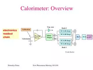
The readout system 192 ECAL FEB 54 HCAL FEB 12-bit ADC 40 MHz 32 channels 1 MHz 100 PS/SPD FEB 10-bit ADC 40 MHz 1 MHz 64 channels 40 MHz 40 MHz Pascal Perret - LPC Clermont
The readout system 192 ECAL FEB 54 HCAL FEB 12-bit ADC + backplanes 40 MHz 32 channels • Common readoutelectronicsused as much as possible 1 MHz 100 PS/SPD FEB 10-bit ADC 40 MHz 1 MHz 64 channels 40 MHz 40 MHz Pascal Perret - LPC Clermont
SPD-PS Very front-end Front-end Crates Power Supply The readout system Y~7m X~8.5m PS/SPD HCAL ECAL • In a same rack: • 1 PS crate • 2 ECAL crates • ECAL/HCAL • platformsmovingwith the detector • Each ½ detector canbemovedindependly Z~2.7m Pascal Perret - LPC Clermont
LHCbCalorimeter System HCAL PS/SPD ECAL Pascal Perret - LPC Clermont • Used to measure energy and to identify e, , 0, h • at the fast Level-0 trigger (@40 MHz) to identify high ET particles that could sign a B decay: • SPD/PS/ECAL/HCAL in coincidence
Electromagnetic Clusters SPD-lead-PS HCAL ECAL Pascal Perret - LPC Clermont • Electromagnetic particles will deposit their energy inside ECAL • The energy deposit in PS is added (offline) • Most of the energy contained in a quartet of cells • Cell size of inner part close to the “Moliere” radius: • SPD & PS validate the charged and EM nature of incoming particle, respectively
L0 CALO: Cluster Algorithm SPDPbPS ECAL e- Pascal Perret - LPC Clermont • Detect a local high ET cluster in ECAL (or HCAL) • Cluster = 2x2 cells • ECAL: • Validation by PS/SPD (same geometry) to get e and candidates • HCAL : • Add the ECAL ET in front if available • Synchronous processing, integrated in the FE card to minimise the connections • Only the highest ET candidate is searched for • Select locally as much as possible • Access to neighbours is the key issue • Easy on the same board • Dedicated backplane for most of the links • Short (2-10 m) LVDS cables for the rest
Hardware implementation Pascal Perret - LPC Clermont • Mostly on top of the calorimeter • Radiation (<10 Gy/year) and SEU impose to use anti-fuse PGA and triple voting techniques • First step is integrated in the FE cards • Calorimeter FE card for cluster search • Preshower FE card for access to SPD/Preshower • Only one extra PGA on each card • Dedicated backplane for as many links as possible • Two Validation cards in each ECAL crate • To combine the various information, and reduce the number of candidates (ECAL+HCAL sum done, the highest sum sent to the SB) • 28 cards needed • About 200 optical links • To send the candidates for final processing in the barracks
Hardware implementation Pascal Perret - LPC Clermont • Selection Crate for final selection • Outputs only the best candidate (highest ET) in each category • Electron, photon, π0, hadron • Provide also global variables • Total SPD multiplicity, to reject dirty events • Total ET, toreject empty crossing (no interaction) that may be triggered by halo muon • Eight identical boards needed, seven quantities sent to L0DU • Level-0 Decision Unit (L0DU) • Apply thresholds on highest ET and pT • Combine information • Send decision to Time Fast Control (TFC) • Send data to HLT and DAQ • Fully synchronous system • Latency under control:4 μs allowed
Hardware implementation ECAL Crate Storage Concrete WALL DAQ SelectionBoard TFC ECS Control Room Pascal Perret - LPC Clermont
L0 CALO performances L0 hadron L0 electron From B0 J/(e+e-) K*0 Pascal Perret - LPC Clermont • Main L0 lines and rates used in 2011 (=870 kHz):[arXiv:1211.3055]
Photodetectors PMT and CW base PMT CW base Pascal Perret - LPC Clermont • SPD/PS • 64-anodes PMT (Hamamatsu R7600) • Pixel size: 2x2 mm2 • Average light yield: ~20 p.e. /MIP • SPD: Mean HV~560V • PS: Mean HV~530V • ECAL/HCAL • Hamamatsu R7899-20 • ECAL • Average light yield:~3000 p.e./GeV • Mean HV ~760V • HCAL • Average light yield:~105 p.e./GeV • Mean HV ~1100V
LED pulse 50 GeV e- LED monitoring system Pascal Perret - LPC Clermont • Aim: • Check readout channels serviceability • Control the stability of r/o chains • ECAL: • Small pulse duration and dispersion of amplitude • Adjustable pulse rate and amount of light • Emulate e/m particles in full “physics” region • Gain control to better than 1% accuracy • Control only electronics chain • supply LED light directly to the PMT • Use empty bunches for running monitoring system
… LED Driver LED LED LED LED LED PMT LED LED LED LED LED LED Splitter ADC PIN diode LED monitoring system 0.2% Monitoring of LED with PIN diode Pascal Perret - LPC Clermont • ECAL: • 512 LED drivers & LEDs & splitters & fiber-bundles • 1 LED illuminates a group of channels • 9 in the Inner, 16 in the Middle/Outer sections • Stability of LEDs themselves is traced by PIN photodiodes: 64 PIN-diodes
LED monitoring system Pascal Perret - LPC Clermont • HCAL • Two independent LEDs per module • Blue LEDs (WU-14-750BC) • Adjustable LED pulse amplitude • Monitoring PIN photodiode at each LED in order to account for LED instability • Light distribution with clear fibers of same length
Calibration system of HCAL • System of dedicated integrators measures PM anode currents every 5 ms • Boards installed at the back of the HCAL nearby PMTs. • Readout via the slow control bus (SPECS) • Currents in HCAL cells are continuously monitored during physics data taking • Absolutenormalization ~10%, dominated by the uncertainty in the source activity • Cell to cellintercalibrationbetterthan 4% • Calibration doneregularly Pascal Perret - LPC Clermont • Two ~ 10 mCi137Cs source used: • 1 per each detector half • Driven by hydraulic system • Similar to the ATLAS TileCal one • Each source propagates consecutively through 26 HCAL modules with an average velocity of about 20–40 cm/s.
Commissioning & Operation Pascal Perret - LPC Clermont
Commissioning & Operation Pascal Perret - LPC Clermont • Major issues • Time alignment • Internal alignment of each detector (individual channels) • Relative alignment of the calorimeter subdetectors with each other • Absolute alignment with LHCb and accelerator cycle • Calibration • Absolute calibration of detector response on the level of individual cells • Stability • Monitoring of the stability of calorimeters with LED / PIN systems • Done in parallel with data taking: • LEDs are fired synchronously with one of “empty” bunches with frequency ~50 Hz
Commissioning & Operation TI8 LHC OT ~340 m Calo Muon Pascal Perret - LPC Clermont • The tools • LED system + Cs source for HCAL • Cosmic rays • Few Hz of “horizontal” cosmic tracks: O(M) events • Cosmics come from top • Slope gives direction, and then time-of-flight corrections • LHC injection events • Transfer line External beam Dump (TED) • Shots every 48 seconds • ~10 particles/cm2 • Collisions
Time alignment [JINST 7 (2012) P08020] δTsampling Shape of the integrated signal 25 ns Next1 T0 t Pascal Perret - LPC Clermont • ECAL/HCAL (essentially same method for SPD/PS) • Pulse shape known • LHCb DAQ may be configured to perform the acquisition of up to 7 successive events around the collision (TAE) • Extract time of crossing particle from Asymmetry between current and next signal amplitude • Best timing sensitivity obtained when half-detector shifted by 12.5 ns • Precision achieved <1 ns
Calibration ~95% efficient for MIPs Pascal Perret - LPC Clermont • SPD/PS • SPD: threshold set at ~0.5 MIP • PS: MIP signal set at ~10 ADC count • Fit the MIP signal and look for efficiencies • ECAL/HCAL • HV are set sothat the PMT responseis the same over the entiredetector for the sameET • ET=E sinqwhereqis the angle between the beam and the line from the collision point to the position of the cell. • ETpTfor chargedtracksbecause of the bending of the magnet, and the relation between ET and pTdepends on the charge of the track and on the magnetpolarity. • ECAL: LED system, Fit p0mass, E/p for electrons, etc. • HCAL: LED system,Radioactive 137Cs source, E/p hadrons, etc. • Two places to adjust the calibration: • Gain of the PMT, • Constants in the electronics.
SPD/PS calibration • Collect data at different thresholds and get efficiency to MIP by comparing with theoretical value • Provide a resolution in the MIP position smaller than 5% • limited by electronics (Electronic resolution for setting the value of the threshold value is 5% of EMIP) • ~10% achieved with cosmics Theoreticalefficiency ε = LandauxPoisson Fluctuations of nphe at photocathode. Energyloss Pascal Perret - LPC Clermont • Performed first with cosmic rays then with collisions • SPD • Binary detector: no straight MIP calibration
SPD/PS calibration Typical charge distribution for extrapolatedtracks INNER • Use any reconstructed track which extrapolation hits the Preshower • MIP signal is fitted (LandauGauss) and fixed to a given number of ADC counts • ~5% precisionlevel • Cross-check withEnergy flow method • Smoothing of the local energydeposit • Average over neighbourchannels • ~4% precisionlevel Pascal Perret - LPC Clermont • Performed first with cosmic rays then with collisions • PS
SPD/PS calibration Typical charge distribution for extrapolatedtracks • Use any reconstructed track which extrapolation hits the Preshower • MIP signal is fitted (LandauGauss) and fixed to a given number of ADC counts • ~5% precisionlevel • Cross-check withEnergy flow method • Smoothing of the local energydeposit • Average over neighbourchannels • ~4% precisionlevel • Absolute calibration fromp0widthminimisation (or electron) Erec= αEcluster + βEps (dependsonbarycenter position insidethecluster and insidethe module) Preshowercorrection (determination for e, ) Pascal Perret - LPC Clermont • Performed first with cosmic rays then with collisions • PS
ECAL calibration Reference point G • Measurement of the normalized dependence G(HV) with respect to the reference point: • according to the change of PM response • Intercalibration of ~6% at start ECAL Operating range G = G0HV HV(kV) Pascal Perret - LPC Clermont • Pre-calibration with the LED monitoring system • Performed in 2 steps: • Measurement of absolute value of G in the reference point • Width of the distribution of PM responses on LED is defined by photostatistics ~√Np.e. G = К *(σ(LED)² - σ(pedestal)²) / (A(LED) – A(pedestal)) К – parameter, defined by hardware properties (ADC sensitivity, modules light yield, etc)
ECAL calibration Mass = 133 ± 3 MeV σ = 11 ± 4 MeV Di-photon invariant mass distribution, MeV/c² LHCb DATA 2009 • 0 calo-standaloneselection: • ET () > 200 MeV • (no track veto) • EPS >10 MeV && no-SPD Pascal Perret - LPC Clermont Clear observation of p0→ signal immediately after the LHC startup in the end of 2009
ECAL calibration 2011 data (June) Preliminary • 0selectioncuts: • No SPD hit • pT()>300 MeV • EPS<10 MeV • (only ECAL calibration) • pT (0)>800 MeV Initial calibration value Absolute calibration iterations Final calibration value Pascal Perret - LPC Clermont • Absolute calibration usingreconstructedp0peak • Iterativeprocedure by p0 mass peakfitting • Select photons (3x3 clusters) and fix seed (central) cell • Compute di-photon invariant mass • Findthe coefficient whichwould move the measured mass closer to the p0nominal one: = Mnom/Mmeas = 135 MeV / Mmeas • Repeat for each cell (6096) • Iterate until stable • ~1-2% precision
ECAL calibration 2010 data Preliminary Inner zone • Where: • N: total number of tracks (e-candidates), • M: number of cells in ECAL cluster from i-th track, • EPRS: the energy deposited in Preshower detector, • : weight factor for Preshowerenergy deposition, • pi:momentum of i-th track, • kj:j-th element of the vector k of calibration coefficients, • Eij:energy deposition in j-th cell of ECAL cluster from i-thtrack, • i : energy resolution of ECAL for current track. Before Afterminimization E/p Pascal Perret - LPC Clermont • Calibration withelectrons • Isolatedelectrons • Defined pure electronsampleswith the RICH detectors • No charged tracks within circle with R = 30 cm at ECAL entrance • Comparison of the total energy of the charged cluster in ECAL (+ PS) to the momentum of tracks for electron-candidates • Minimization of
HCAL calibration LED 1 noisy channel Radioactivesource 2 dead cells Pascal Perret - LPC Clermont • 3 steps to ensure correction calibration: • LED system • This gives the relative variation of the PMT • Cs source • Allows the absolute calibration of the scintillatorresponse • Monte Carlo simulation • The missing step is the knowledge of the complete module response (Iron + scintillator + all materiel in front of the HCAL) to particles • The ratio « Measured energy in the scintillator/Energy of the particle when produced » is taken from Monte Carlo (ie Geant4), for pions. • ~5% precision (design of the HCAL)
Stability 3% Pascal Perret - LPC Clermont • Unstability: PMT • Rate effects: but reproduced at each run • Addition of an extra 11 kHz of periodic triggers for ECAL & HCAL LED flashing • Ageing • Combination of several effects: • PMT ageing as a function of the integrated current (PMT dynode) • Depends upon cell size and location • Scintillator ageing due to radiations • Plastic tiles become less and less transparent • Proportional to particule flux (neutral + charged) • These are wellknownunavoidableeffects…
ECAL ageing Red: physics runs - Black: the rest Inner: up to 5.7% Middle: up to 3.8% Outer: up to 4.1 % #92035 1799 21/5/11 #93995 1883 21/6/11 Time, minutes. One point per run ~300 pb-1 Pascal Perret - LPC Clermont • LED monitoring system can be used to follow ECAL ageing • Comparison of LED response (PIN corrected) for different fills: Average relative PmToPin change with respect to 1st run (fill 1799)
ECAL: LED • Degradation of clear fibers due to radiation damage • The ECAL LED monitoring system cannot be used to monitor (simply!) ECAL ageing… PmToPin(93995) /PmToPin(92035) Pascal Perret - LPC Clermont Changes are more pronounced in inner section but …