Download
1 / 56
610 likes | 1.14k Vues
Static Routing. Routing Protocols and Concepts – Chapter 2 Sandra Coleman, CCNA, CCAI. Objectives. Define the general role a router plays in networks. Describe the directly connected networks, different router interfaces

E N D
Static Routing Routing Protocols and Concepts – Chapter 2 Sandra Coleman, CCNA, CCAI
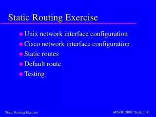
Objectives • Define the general role a router plays in networks. • Describe the directly connected networks, different router interfaces • Examine directly connected networks in the routing table and use the CDP protocol • Describe static routes with exit interfaces • Describe summary and default route • Examine how packets get forwarded when using static routes • Identify how to manage and troubleshoot static routes • Green highlights are for testing purposes!
General Role of the Router • Functions of a Router • Best Path Selections • Forwarding packets to destination • Introducing the Topology • 3 1800 series routers connected via WAN links • Each router connected to a LAN represented by a switch and a PC
General Role of the Router • Connections of a Router for WAN • -A router has a DB-60 port that can support 5 different cabling standards • Connections of a Router for Ethernet • -2 types of connectors can be used: Straight through and Cross-over • Straight through used to connect: • -Switch-to-Router, Switch-to-PC, Router-to-Server, Hub-to-PC, Hub-to-Server • Cross-over used to connect: • -Switch-to-Switch, PC-to-PC, Switch-to-Hub, Hub-to-Hub, Router-to-Router, PC-to-Router via Ethernet
Packet Tracer Activity (pg. 71 textbook) • Start packet tracer • Load e2-213.pka from ‘Public/CCNA2 Packet Tracer Files/Text book’ and do this… • If you have problems…let me know • Follow the instructions…don’t try to SAVE it on top of what is there, simply follow the instructions and then click the ‘CHECK RESULTS’ button. • When you get finished and it is 100% correct, let me see. You’ll get a homework grade for this.
Interfaces • Examining Router Interfaces • -Show IP route– used to view routing table • -Show Interfaces command – used to show status of an interface and details about it • -Show IP Interface brief command – BEST ONE to use to quickly find the status of interfaces and IP addresses! • -Show running-config command – used to show configuration file in RAM (can be show run)
Interfaces • Configuring an Ethernet interface • -By default all serial and Ethernet interfaces are down • -To enable an interface use the No Shutdown command
Interfaces • Verifying Ethernet interface • -Show interface fastEthernet 0/0 – command used to show status of fast Ethernet port • -Show ip interface brief – see status of lines and IP addresses • -Show running-config • Ethernet interfaces participate in ARP
Routing Table comparison • The phone book only contains one listing for each phone number. For example, the Stanford family might be listed as: • Stanford, Harold, 742 Evergreen Terrace, 555-1234 • This is the single entry for everyone who lives at this address and has the same phone number. The phone book could contain a listing for every individual, but this would increase the size of the phone book. For example, there could be a separate listing for Harold Stanford, Margaret Stanford, Brad Stanford, Leslie Stanford, and Maggie Stanford - all with the same address and phone number. If this were done for every family, the phone book would be larger and take longer to search. • Routing tables work the same way: one entry in the table represents a "family" of devices that all share the same network or address space (the difference between a network and an address space will become clearer as you move through the course). The fewer the entries in the routing table, the faster the lookup process. To keep routing tables smaller, network addresses with subnet masks are listed instead of individual host IP addresses.
Packet Tracer Activity (pg. 81) • Start Packet Tracer • Open file e2-223.pka from ‘Public/CCNA2 Packet Tracer Files/Textbook’ • DON”T SAVE it! • Finish it and press the Check Results button so that I can see it.
Interfaces • Configuring a Serial interface • -Enter interface configuration mode • -Enter in the ip address and subnet mask • -Enter in the no shutdown command • Example: • -R1(config)#interface serial 0/0 • -R1(config-if)#ip address 172.16.2.1 255.255.255.0 • -R1(config-if)#no shutdown
Examining Router Interfaces • -Physically connecting a WAN Interface. • -A WAN Physical Layer connection has sides: • Data Circuit-terminating Equipment (DCE) – This is the service provider. CSU/DSU is a DCE device. MUST configure clock rate HERE! • Data Terminal Equipment (DTE) – Typically the router is the DTE device. • Administratively downmeans that the interface is currently in the shutdown mode, or turned off. Line protocol is down means, in this case, that the interface is not receiving a carrier signal from a switch or the hub. This condition may also be due to the fact that the interface is in shutdown mode. • If you do not correctly set the clock rate on a serial interface, then line protocol (the Data Link layer) will not change to up. • No carrier signals also will keep the protocol down (missing 3 keepalives will bring the line down)
Example of CSU/DSU and router Function of CSU/DSU or modem: Responsible for converting data from the WAN ISP into a form that is acceptable by the router. DTE device is on user’s end of WAN link DCE device is on ISP end of the WAN link csu/dsu
Interfaces • Configuring serial links in a lab environment • One side of a serial connection must be considered a DCE • This requires placing a clocking signal – use the clock rate command. • Example: • -R1(config)#interface serial 0/0 • -R1(config-if)#clockrate 64000 (sometimes clockrate is 2 words – depends on the router) • Serial Interfaces require a clock signal to control the timing of the communications. • To determine if you have a DTE or DCE cable attached, use the show controllers serial command.
Logging Synchronous • In order to keep the unsolicited output separate from your input, enter line configuration mode for the consoled port and add the logging synchronous. You will see that messages returned by IOS no longer interfere with your typing.
Routing Tables • The main purpose of a routing table is to provide the router with paths to different destination networks. • Remember, routers need to know how to get to the NETWORK the packet is on. • It is the switch’s job to get to the exact IP address! • To remove a directly connected network from a router, use these two commands: shutdown and no ip address.
Debug commands • Purpose of the debug ip routing command • Allows you to view changes that the router performs when adding or removing routes • Example: • -R2#debug ip routing • -IP routing debugging is on • Debug commands, especially the debug all command, should be used sparingly. These commands can disrupt router operations. • Debug commands are useful when configuring or troubleshooting a network; however, they can make intensive use of CPU and memory resources.
Routing Table • When a router only has its interfaces configured&no other routing protocols are configured then: • -The routing table contains only the directly connected networks • -Only devices on the directly connected networks are reachable
Reading routing tables (pg. 97-example) • the address must match the number of left-most bits of the network address as indicated by the prefix of the route. For R2, all the routes have a /24 prefix, therefore, the left-most 24 bits are checked for each route.
Routing Table and CDP Protocol • Checking each route in turn • The ping command is used to check end to end connectivity
CDP – Cisco Discovery Protocol • Cisco Discovery Protocol (CDP) is a powerful network monitoring and troubleshooting tool. • CDP is an information-gathering tool used by network administrators to get information about directly connected Cisco devices. • CDP is a proprietary tool that enables you to access a summary of protocol and address information about Cisco devices that are directly connected. • By default, each Cisco device sends periodic messages, which are known as CDP advertisements, to directly connected Cisco devices. These advertisements contain information such as the types of devices that are connected, the router interfaces they are connected to, the interfaces used to make the connections, and the model numbers of the devices.
CDP Protocol • Purpose of CDP • A layer 2 cisco proprietary tool used to gather information about other directly connected Cisco devices. • Concept of neighbors • -2 types of neighbors • Layer 3 neighbors • Layer 2 neighbors
Routing Table and CDP Protocol • CDP show commands • Show cdp neighbors command • -Displays the following information: • Neighbor device ID • Local interface • Holdtime value, in seconds • Neighbor device capability code • Neighbor hardware platform • Neighbor remote port ID • Show cdp neighbors detail command • -Useful in determining if an IP address configuration error (I have had to use this on the CCNA test several times to find addresses to connecting devices that were not CLICKABLE)
Routing Table and CDP Protocol • CDP starts up automatically and allows the device to detect directly connected neighbors • Devices can learn about each other REGARDLESS of the routing protocol being used. • Disabling CDP • To disable CDP globally use the following command • Router(config)#no cdp run • To stop CDP advertisements on a particular interface, use the following command: • Router(config-if)#no cdp enable
Learning routes • Static • Manually configured by network admin • Dynamic • From a dynamic routing protocol (from a neighbor)
Static Routes • Purpose of a static route • A manually configured route used when routing from a network to a stub network (network accessed by a single route) • Only one way out of R1 for sending non-local traffic, so it would be a waste of resources to run a routing protocol between R1 and R2 – set up a static route on R2 to the LAN on R1.
Static Routes • IP routecommand • To configure a static route use the following command: ip route • Example: • -Router(config)# ip route network-address subnet-mask {ip-address | exit-interface }
Static Routes • Dissecting static route syntax • ip route - Static route command • 172.16.1.0 – Destination network address • 255.255.255.0 - Subnet mask of destination network • 172.16.2.2 - Serial 0/0/0 interface IP address on R2, which is the "next-hop" to this network
Static Routes • Configuring routes to 2 or more remote networks • (on test…choose correct command) • Use the following commands for R1 • -R1(config)#ip route 192.168.1.0 255.255.255.0 172.16.2.2 • -R1(config)#ip route 192.168.2.0 255.255.255.0 172.16.2.2
Static routes Referring to the graphic, you can see that static routes have an administrative distance of 1 and a metric of 0
Static Routes • Zinin’s 3 routing principles • Principle 1: "Every router makes its decision alone, based on the information it has in its own routing table.“ • Principle 2: "The fact that one router has certain information in its routing table does not mean that other routers have the same information.“ • Principle 3: "Routing information about a path from one network to another does not provide routing information about the reverse, or return path."
Static Routes with Exit Interfaces • Using Zinin’s 3 routing principles, how would you answer the following? -Would packets from PC1 reach their destination? • Yes, packets destined for 172.16.1.0/24 and 192.168.1.0/24 networks would reach their destination. • -Does this mean that any packets from these networks destined for 172.16.3.0/24 network will reach their destination? • No, because neither R2 nor R3 router has a route to the 172.16.3.0/24 network.
Static Routes with Exit Interfaces • Resolving to an Exit Interface • Recursive route lookup - Occurs when the router has to perform multiple lookups in the routing table before forwarding a packet. A static route that forwards all packets to the next-hop IP address goes through the following process (reclusive route lookup) (Be prepared to do this on the test, looking at a routing table) • The router first must match static route’s destination IP address with the Next hop address • The next hop address is then matched to an exit interface
Static Routes with Exit Interfaces • Configuring a Static route with an Exit Interface • -Static routes configured with an exit interface are more efficient because the routing table can resolve the exit interface in a single search instead of 2 searches NO RECURSIVE LOOKUPS REQUIRED! • -Example of syntax require to configure a static route with an exit interface
Resolving an exit interface • What if an interface goes down? • If the static route can NOT be resolved, it is REMOVED from the routing table!
Static routes • Find this line in the routing table: • S 192.168.2.0/24 is directly connected, Serial0/0/0 • Now, when the routing table process has a match for a packet and this static route, it will be able to resolve the route to an exit interface in a single lookup. As you can see in the figure, the other two static routes still must be processed in two steps, resolving to the same Serial 0/0/0 interface.
Static Routes • Modifying Static routes • Existing static routes cannot be modified. The old static route must be deleted by placing no in front of the ip route • Example: -no ip route 192.168.2.0 255.255.255.0 172.16.2.2 • A new static route must be rewritten in the configuration
When to alter routes! • A network admin might need to alter a static route if • A destination network no longer exists • Next-hop address or exit interface becomes inaccessible
Static Routes with Exit Interfaces • Verifying the Static Route Configuration • -Use the following commands • Step 1 show running-config • Step 2 verify static route has been entered correctly • Step 3 show ip route • Step 4 verify route was configured in routing table • Step 5 issue ping command to verify packets can reach destination and that Return path is working
Static Routes with Exit Interfaces • Ethernet interfaces and ARP. • If a static route is configured on an Ethernet link • -If the packet is sent to the next-hop router then… • the destination MAC address will be the address of the next hop’s Ethernet interface • A router CANNOT determine the next-hop MAC address for a frame without a next-hop address on the Static route
Solution to Ethernet interfaces • Is there any way to configure a static route over an Ethernet network so that it does not have to use the recursive lookup of the next-hop IP address? Yes - this can be done by configuring the static route to include both the exit interface and the next-hop IP address. • As you can see in the previous figure, the exit interface would be FastEthernet 0/1 and the next-hop IP address would be 172.16.2.2. • R1(config)#ip route 192.168.2.0 255.255.255.0 fastethernet 0/1 172.16.2.2 • The routing table entry for this route would be: • S 192.168.2.0/24 [1/0] via 172.16.2.2 FastEthernet0/1 • The routing table process will only need to perform a single lookup to get both the exit interface and the next-hop IP address.
Summary and Default Route • Summarizing routesreduces the size of the routing table. • Route summarization is the process of combining a number of static routes into a single static route.
Calculating Summary routes (on test!) • 1. Write out the networks that you want to summarize in binary. • 2. To find the subnet mask for summarization, start with the left-most bit. • 3. Work your way to the right, finding all the bits that match consecutively. • 4. When you find a column of bits that do not match, stop. You are at the summary boundary. • 5. Now, count the number of left-most matching bits, which in our example is 22. This number becomes your subnet mask for the summarized route, /22 or 255.255.252.0 • 6. To find the network address for summarization, copy the matching 22 bits and add all 0 bits to the end to make 32 bits.
Summary and Default Route You will have to do this on the Chapter 2 onlineTest! • Configuring a summary route • Step 1: Delete the current static route • Step 2: Configure the summary static route • Step 3: Verify the new static route
Summary and Default Route • Default Static Route • This is a route that will match all packets. Stub routers that have a number of static routes all exiting the same interface are good candidates for a default route. • -Like route summarization this will help reduce the size of the routing table • Configuring a default static route (know this!) • Similar to configuring a static route. Except that destination IP address and subnet mask are all zeros • Example: • -Router(config)#ip route 0.0.0.0 0.0.0.0 [exit-interface | ip-address ]
Summary and Default Route • Static routes and subnet masks • The routing table lookup process will use the most specific match (the one with the MOST # of bits in common with the packet – look at the CIDR notation to see which one is the closest match – that’s what determines how many bits must match) when comparing destination IP address and subnet mask • Default static routes and subnet masks • Since the subnet mask used on a default static route is 0.0.0.0 all packets will match. • Default routes are VERY COMMON. Instead of having to store many routes for all the networks on the Internet, the can store a single default route to represent ANY network not in the routing table.
Finding the BEST route in the routing table • It is possible that the destination IP address of a packet will match multiple routes in the routing table. For example, what if we had the following two static routes in the routing table: • 172.16.0.0/24 is subnetted, 3 subnets • S 172.16.1.0 is directly connected, Serial0/0/0 and • S 172.16.0.0/16 is directly connected, Serial0/0/1 • Consider a packet with the destination IP address 172.16.1.10. This IP address matches both routes. • The routing table lookup process will use the most-specific match. Because 24 bits match the 172.16.1.0/24 route, and only 16 bits of the 172.16.0.0/16 route match, the static route with the 24 bit match will be used. This is the longest match. • The packet will then be encapsulated in a Layer 2 frame and sent via the Serial 0/0/0 interface. Remember, the subnet mask in the route entry is what determines how many bits must match the packet's destination IP address for this route to be a match.
Static Routes and Packet Forwarding • Packet forwarding with static routes. (recall Zinin’s 3 routing principles) • Router 1 • Packet arrives on R1’s Fastethernet 0/0 interface • R1 does not have a route to the destination network, 192.168.2.0/24 • R1 uses the default • static route.
Static Routes and Packet Forwarding • Packet forwarding with static routes. (recall Zinin’s 3 routing principles) • Router 2 • The packet arrives on the Serial 0/0/0 interface on R2. • R2 has a static route to 192.168.2.0/24 out Serial0/0/1.