Download
1 / 23
280 likes | 391 Vues
Wired LANs: Ethernet. IEEE STANDARDS. The LAN market has several technologies such as Ethernet, Token Ring, Token Bus, FDDI, and ATM LAN.

E N D
IEEE STANDARDS The LAN market has several technologies such as Ethernet, Token Ring, Token Bus, FDDI, and ATM LAN. In 1985, the Computer Society of the IEEE started a project, called Project 802, to set standards to enable intercommunication among equipment from a variety of manufacturers. Project 802 is a way of specifying functions of the physical layer and the data link layer of major LAN protocols. Topics discussed in this section: Data Link LayerPhysical Layer
Figure IEEE standard for LANs The IEEE has subdivided data link layer into two sublayers: logical link control (LLC) and media access control (MAC).
Logical Link Control • In IEEE Project 802, flow control, error control and part of framing duties are collected into one sublayer called the logical link control. • The LLC provides one single data link control protocol for all IEEE LANs. • A single LLC protocol can provide interconnectivity between different LANs because it makes the MAC sublayer transparent. Framing • LLC defines a Protocol data unit(PDU) has the header field which is used for flow and error control. • The two other header fields define the upper-layer protocol at the source and destination that uses LLC – destination service access point and source service access point.
Medium Access Control • It specifies the media access method for each LAN. • For example, it defines CSMA/CD as the media access method for Ethernet LANs and the token-passing method for Token Ring and Token Bus LANs. • It defines the access method and the framing format specific to corresponding LAN protocol.
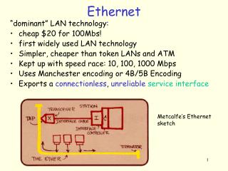
STANDARD ETHERNET The original Ethernet was created in 1976 at Xerox’s Palo Alto Research Center (PARC). Since then, it has gone through four generations. We briefly discuss the Standard (or traditional) Ethernet in this section. Topics discussed in this section: MAC SublayerPhysical Layer
MAC Sublayer • In standard Ethernet, the MAC sublayer governs the operation of the access method. • It also frames data received from the upper layers and passes them to the physical layer. Frame Format • Ethernet does not provides any mechanism for acknowledging received frames. • This frame contains 7 fields: preamble, SFD, DA, SA, length or type of protocol data unit, upper-layer data and CRC.
Note Frame length: Minimum: 64 bytes (512 bits) Maximum: 1518 bytes (12,144 bits)
Addressing • Each station on an Ethernet network has its own Network Interface Card (NIC). • The NIC fits inside the station and provides the station with a 6-byte physical address. • The Ethernet address is a 6-byte(48 bits), normally written in hexa-decimal notation, with a colon between bytes. Figure Example of an Ethernet address in hexadecimal notation
Unicast, multicast and broadcast addresses • A source address is always a unicast address- the frame comes from only one station. • The destination address, however, can be unicast, multicast or broad cast address. • If the least significant bit for the first byte in a destination address is 0, the address is unicast; otherwise it is multicast. • A unicast destination address defines only one recipient and the relationship between sender and receiver is one-to-one. • A multicast destination address defines a group of addresses and the relationship between sender and receiver is one-to-many. • The broadcast address is a special case of multicast address and the recipients are all the stations in the LAN.
Note The least significant bit of the first byte defines the type of address.If the bit is 0, the address is unicast;otherwise, it is multicast.
Note The broadcast destination address is a special case of the multicast address in which all bits are 1s.
Example 13.1 Define the type of the following destination addresses: a. 4A:30:10:21:10:1A b. 47:20:1B:2E:08:EE c. FF:FF:FF:FF:FF:FF Solution To find the type of the address, we need to look at the second hexadecimal digit from the left. If it is even, the address is unicast. If it is odd, the address is multicast. If all digits are F’s, the address is broadcast. Therefore, we have the following: a. This is a unicast address because A in binary is 1010. b. This is a multicast address because 7 in binary is 0111. c. This is a broadcast address because all digits are F’s.
Carrier Sense Multiple Access with Collision Detection (CSMA/CD) • When a station has data to transmit, it first listens to the cable to see if a carrier(signal) is being transmitted by another station. This may be achieved by monitoring whether a current is flowing in the cable. • Data is sent when no carrier is observed and the physical medium is therefore idle. • The collision will result in the corruption of the frame being sent, which is subsequently be discarded by the receiver. • This may happens when two stations send the data at the same time when the medium is idle. • CSMA/CD augments the algorithm to handle the collision. • In this method, a station monitors the medium after it sends a frame to see if the transmission was successful. • If so the station is finished. If however, there is a collision, the frame is sent again.