Download
1 / 25
250 likes | 400 Vues
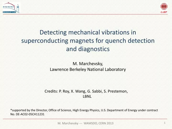
Detecting mechanical vibrations in superconducting magnets for quench detection and diagnostics. M. Marchevsky , Lawrence Berkeley National Laboratory. Credits: P. Roy, X. Wang, G. Sabbi , S. Prestemon , LBNL.

E N D
Detecting mechanical vibrations in superconducting magnets for quench detection and diagnostics M. Marchevsky, Lawrence Berkeley National Laboratory Credits: P. Roy, X. Wang, G. Sabbi, S. Prestemon, LBNL *supported by the Director, Office of Science, High Energy Physics, U.S. Department of Energy under contract No. DE-AC02-05CH11231
Outline • Motivation for mechanical vibration (acoustic) sensing and earlier developments in the field • Magnets as mechanical resonators • Instrumentation for acoustic sensing • Case study: correlation of acoustic and voltage imbalancesignals in the recent HQ magnet test (HQ01e3) • Inductive sensing of mechanical vibrations and conductor motion • Future plans
Why acoustic sensing? • Voltage taps: this approach is not optimal for longer magnets and may be not viable in newer complex magnet geometries (multi-layers, etc.) • Magnetic quench antennas: data requires significant post-processing; permanent access to the bore or adaptation to the magnet geometry is needed • Advantages of sensing sounds for magnet diagnostics: • Propagation velocity is large (several km/s), so that detection can be accomplished on a time scale that is comparable (or faster) to other techniques • Using sensor arrays, sound sources can be localized with a few cm accuracy through triangulation • Selectivity for different kinds of events, through frequency and phase analysis • Outer surfaces sensor mounting for non-intrusive detection • Immunity to magnetic fields • Sensors and acquisition hardware are relatively inexpensive, portable and easily adaptable to various magnet configurations
Earlier developments Dislocation motion and micro-plasticity -> technical superconductors stability -> superconducting magnets training -> active acoustic monitoring of SC magnets • P. P. Gillis, “Dislocation motion and acoustic emission”, ASTM STP 505, 20-29, 1972 • “Dynamic stress effects in technical superconductors and the "training" problem of superconducting magnets”, G. Pasztor and C. Schmidt, J. Appl. Phys. 49, 886 (1978) • H. Brechna and P. Turowski, “Training and degradation phenomena in superconducting magnets,” Proc. 6th Intl. Conf. Magnet Tech. (MT6) (ALFA, Bratislava, Czechoslovakia) 597, (1978). • “Acoustic emission from NbTi superconductors during flux jump”, G. Pasztor and C. Schmidt, Cryogenics 19, 608 (1979). • “Sources of acoustic emission in superconducting magnets”, O. Tsukamotoand Y. Iwasa, J. Appl. Phys. 54, 997 (1983). • “Discussion on acoustic emission of a superconducting solenoid”, M. Pappe, IEEE Trans. on Magn., 19, 1086 (1983) • “Acoustic emission monitoring results from a Fermi dipole”, O.O. Ige, A,D. Mclnturf and Y. Iwasa, Cryogenics 26, 131, (1986) • “Mechanical Disturbances in Superconducting Magnets-A Review”, Y. Iwasa, IEEE Trans on Magn, 28 113 (1992)
Sound generation in superconducting magnets Singular events • Sudden mechanical motion of a cable portion or coil part • Cracking / fracture of epoxy, de-laminations, etc... Potentially, also: • flux jump, as current re-distribution in the cable leads to the local variation of the electromagnetic force • quench development, as formation of a hot spot leads to the local thermal expansion. It that leads to the change in local stress that propagates away with a speed of sound “Singular events” are mostly associated with well-localized sources. They generate longitudinal (pressure) waves that propagate radially from the source with a speed of sound. Wave fronts then gets partially reflected by the boundaries, converted into resonant vibrational modes of the structure and into heat. Continuous perturbations • Mechanical vibrations (various flexural, hoop, “breathing” and other deformation modes of coils, shell and support structures) • Background noise (helium boiling, cryostat vibrations, etc.)
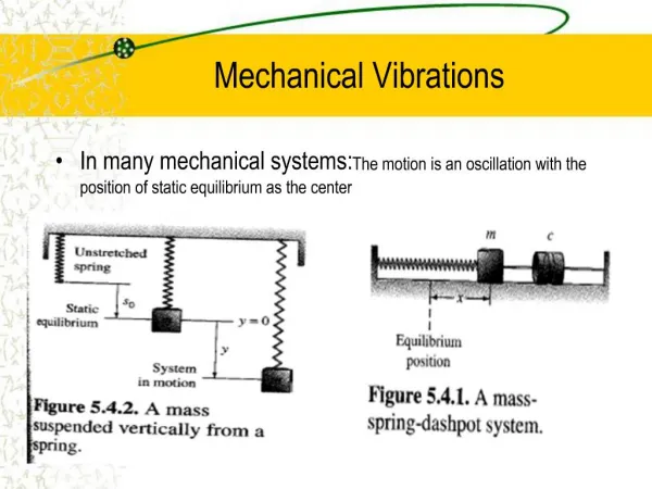
Coils as mechanical resonators Long coils can be thought of as solid “bars” or “rods” Dx Vs where Yis Young modulus and r is the density f1L = Longitudinal (pressure wave) modes: f2L f3L /2L f4L Transverse (flexural) modes of “free” rods: • f1T where L is the length and ais the cross-sectional area f2T=2.76 f1T f3T=5.40 f1T S1 S2 Polarized piezo-ceramics D L Vac
Localization of the sound source 1D Vs Vs t=0 Sensor 1 Sensor 2 t1 t2 Dx - L/2 • Dt12=(t2-t1) = 2Dx/ L/2 • 0 2D (x0,y0) • (x0-x1)2+(y0-y1)2=R12 Sensor 1 • (x0-x2)2+(y0-y2)2=R22 • R1 • R2 • (x0-x3)2+(y0-y3)2=R32 • R3 |R1-R2|=Dt12 • |R1-R3|=Dt13 Sensor 2 Sensor 3 Think GPS !
Instrumentation • Cryogenic preamplifier Piezosensor D • 20 mm . D • GaAs MOSFET-based amplifier • Linear bandwidth of 0-100 kHz • 300 -1.9 K operation temperature range • Converts impedance down to ~1 kW, significantly improves S/N ratio, allows use of regular “twisted pair” connections in the cryostat instead of the coaxes • SM118 type piezoelectric ceramics, polarized across thickness • OD 10 mm x ID 5 mm x Thickness 2 mm, • fr = (154 ± 4) kHz DAQ Software • Yokogawa WE7000 simultaneous multi-channel DAQ system • 100 mV-100 V range • up to 1 MHz speed LabView-based software for waveform analysis, re-sampling and location triangulation of the sound source
Localization tests at RT using HQ Coil 14 R L Dt=0.24 ms Dt=0.01 ms Dt=0.18 ms Sound speed: Vs~ 4.1-4.3 km/s
Installation on the HQ magnet • 2 Sensor 2is installed at the top plate (bolted to the magnet shell) ~130 cm 1 Sensor 1is installed at the bottom load plate (bolted to the axial rods) “Available” (not optimized) locations were used
HQ vibrations resonant spectrum (room temp.) Response to a shell excitation Power spectrum (dB) Response to a rod/load plate excitation Power spectrum (dB)
Extraction at 5.5 kA Original sound slowed down 10 times When current is extracted from the magnet, sounds are recorded (step-like change of elastic strain?), followed by a prolonged (0.5-1 s) “ringing” of the structure at its resonance modes, with occasional “bursts” of mechanical activity (thermal relaxation?) Magnet is a good mechanical resonator with Q~100!
HQ experimental setup • Magnet imbalance signal is formed by subtracting negative half (Coils 5,7) from the negative (Coils 8,9) of the magnet, then amplified x40. • Sound signals from both sensors, magnet imbalance and magnet current are recorded at 1 Ms/s; the time window is 0.2 s. • Acquisition is triggered when either imbalance or sound is above the threshold level. Imag Imag Iq=10870 A 9 kA 75 A/s t 75 A/s t Attempted current ramps
Events during an up-down current ramp RR03: Ramp up to 9 kA and back down Current of the triggered events Sound amplitude of the triggered events • Threshold settings: • Sound: 5 mV • Imbalance: 3 V (amplified; true imbalance threshold is ~75 mV)
Events during a current ramp into quench RR04: Iq=10870 A Ramp to quench at 75 A/s Current at the triggered events Sound amplitude at the triggered events Four possible scenarios are observed: Imbalance variation without any associated sound (below 5 kA) Imbalance variation associated with weak sound signals (below 5 kA) Stronger sounds without association with imbalance variations (above 8.5 kA) Stronger sounds associated with imbalance “spikes” (around 10-10.5 kA)
The 75A/s quench C5 C9 C7 C8 Quench starts in the outer layer multi-turn of C5
Sounds of magnet (low current) • Some imbalance variations at low currents are associated with (weak) sounds! 2440 A 1883 A
Sounds at higher magnet current Much stronger sounds are observed, that are either not correlated with any imbalance variations: or, occasionally, are correlated with a short “spike” in the imbalance signal: 9628 A 10036 A
Origin of the sounds? 2440 A 10036 A The 0.63 ms delay corresponds to the ~2.6 m distance, which would be outside of the magnet length. The sound is likely produced during the (long) imbalance variation, but not at its onset. The 0.11 msdelay corresponds to ~0.46 m distance => the sound is produced within the magnet length. Mechanical motion event is triggering the imbalance? Current re-distribution in the cable triggers sound?
Frequency of the sounds 10248 A Very high frequency sound is detected at Imag>10 kA (Sound slowed down 10x)
Location of the sound sources 10036 A 0.30 ms X= - 63 cm (at the bottom end) It appears that the sources of strong sound generated in HQ01e3 ramps above 9 kA are located near the bottom (return end) of the magnet
“Sound” from the Quench Antennas HQ01d magnet, ramping at 100 A/s Flux jumps Mechanical vibrations Inductive quench antenna is an electromagnetic microphone! It picks up vibrations of the current-carrying (or magnetized) structures By correlating EM QA and piezo-sensor signals, one can potentially differentiate between flux jumps, conductor motion and other mechanical motion in magnets M. Marchevsky et al., ASC 2012 presentation
Future testing opportunities Upcoming test of the high-field dipole magnet HD3 at LBL: We plan to have both, inductive QA and the piezo-sensors installed. QA PS • Proposed positioning of the piezosensorson the magnet: four wedges that are in direct mechanical contact with the windings Upcoming test of the LARP HQ02 magnet: At least two acoustic sensors can be installed on the endplates; some kind of inductive pickup QA may also be installed, t.b.d.
Next steps / challenges • Filtering out the resonant modes and improving selectivity for small signals • Developing microphone arrays and algorithms for precise localization • Quantifying mechanical energy release and conductor motion amplitudes observed with piezo and EM sensors • Acoustic quench detection system?
Conclusions • Amplified piezosensors, in combination with cryo-electronics, modern data acquisition and processing techniques show good potential for real-time characterization of various mechanical events in superconducting magnets during ramping, quench and recovery • HQ magnet produces increased acoustic emissions (seemingly unrelated to FJ) and high-frequency (>50 kHz) vibration “bursts” when energized above 9kA. The latter are occasionally correlated with the short imbalance spikes and most likely caused by stick-slip motion of the conductor • Inductive pickups sensors they provide a unique insight into conductor motion; can be developed and used in conjunction with acoustic devices to improve selectivity for the specific mechanical and electrical events • Listening to magnets sounds like fun!