Download
1 / 17
170 likes | 293 Vues
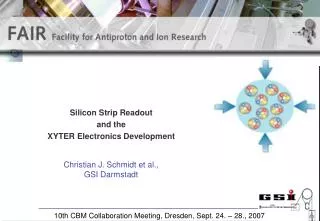
An FPGA Based Readout Scheme Using n-XYTER for CBM Experiment. Our Aim:. To have an Application Specific FPGA Based System & Board using device resources with minimum effort. Requirement for HS Board Design in PCB Level: (a) Precise Footprint for High Density Component

E N D
An FPGA Based Readout Scheme Using n-XYTER for CBM Experiment
Our Aim: • To have an Application Specific FPGA Based System & Board using device resources with minimum effort • Requirement for HS Board Design in PCB Level: (a) Precise Footprint for High Density Component (b) Multi-pass Auto Router (c) SI Tool to address issues like Reflections & Crosstalk • Digital System Design: Using VHDL , FSM Techniques & Device Resource CBM INDIA COLLABORATION MEET
Our Aim: • To analyze Hardware Requirement for FPGA Based DAQ for n-XYTER ASIC • To Design / Configure IP / SOC On FPGA Device with standard periphery • To use Embedded processor in IP / Hard form CBM INDIA COLLABORATION MEET
Our Aim: • To use some standard kernel: Xilkernel & uClinux • To run the application & to estimate the performance of the Configured SOC • To redesign the same with self-designed dedicated core to enhance performance if needed CBM INDIA COLLABORATION MEET
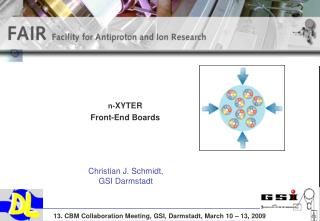
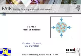
Our Design Approach: Features : n-XYTER Mixed Signal ASIC with CSA Fast & Slow Shaper, PDH,TWC ,Digital & Analog FIFO • No Of Channels: 128 • Data Driven Chip Architecture / Autonomous Hit Detection • Time Stamping with 1 ns resolution • Analog Signal at Readout Clock 32 MHz & Digital Signal at 128 MHz (4 8-bit Packets) 5. 46 Registers for Voltage / Current/ Status / Configuration Configured By IIC bus CBM INDIA COLLABORATION MEET
SPECIFICATIONS OF DETECTORS FOR CBM-XYTER CBM INDIA COLLABORATION MEET
Calculation of Data Rate:- • Data Format • FIFO READ Consists of: (25 BITS + 12 BITS ) • (a) Analog Signal (Pulse Amplitude) 1 analog differential (12) • ( b) Digital Signal: Timestamp(14) +Channel Id(7)+ Datavalid(1) + Pile up(1) +Overflow( 1) IO :Differential 8 LVDS parallel • Hit rate per channel ~ 250kHz • Hit rate all 128 Chnls. = 128 x 250kHz = 32MHz • Digital & Analog Data/ Ch. = 37 Bits (Amp. 12 Bits ,ADC) • Total rate per chip: = 37Bit x 32MHz ~ 1.2Gbps. CBM INDIA COLLABORATION MEET
SELECTION OF ADC : Option 1: One ADC/n-XYTER = 32 MSPS Solution 1: ADS527x(TI) = 20 -70 MSPS Simple Conventional Deserializer Up to 30 MSPS (360Mbps) works fine OPTION 2: One ADC / n Nos. of Chip - Requires more High Speed ADC More SI Problem at High Frequency ; Clock Jitter > 30 MSPS Requires HS Deserializer Hit distribution per n Chip is better than only one per Chip CBM INDIA COLLABORATION MEET
Calculation of Data Rate & Link to next:- LVDS inputs of FPGAs go up to 6.5Mbps → 2 links. A ~ ? Gbps high speed I/O building block could be planned Multi-Gigabit Serial Transceivers in Vertex-4 FX 60 has 12 Channels 1 N-XYTER ASIC & 1 ADC BOARD 1 N-XYTER ASIC & 1 ADC BOARD FPGA Board Gbps Link ? 1 N-XYTER ASIC & 1 ADC BOARD Next FPGA Board with High Link CBM INDIA COLLABORATION MEET
Buffer L1 Select L2 Select Data Push Architecture Detector Self-triggered front-end Autonomous hit detection fclock FEE No dedicated trigger connectivity All detectors can contribute to L1 Cave Shack DAQ Large buffer depth available System is throughput-limited and not latency-limited High bandwidth Slide of Walter F.J. Müller, GSI, Darmstadt Use term: Event Selection Archive CBM INDIA COLLABORATION MEET
A SoC typically consists of a 32-bit core Processor and a set of functions. Functions Include memory, bus interfaces, I/O drivers, decoders and network support FPGA BASED SYSTEM DESIGN USING IP CORE: Embedded PPC405 core Up to 450 MHz : 16 KB I cache & 16 KB : D cache Enhanced I & D OCM ctrl OPB BUS PLB BUS DSOCM (Data & Ad. 32Bits) DDR BRAM IIC SDRAM USB DSOCM GPIO BRAM DSPLB ISPLB INTC DCR Rapid I/O OPB2PLB PPC405 Ethernet PLB2OPB ISOCM INTC ISOCM( Data 64 Bits & Ad.32Bits) BUS OPB ARB PLB ARB BRAM CBM INDIA COLLABORATION MEET
IP cores: • PPC405 and Processor Local Bus • OPB IIC soft Parametric IP core • PLB RapidIO LVDS • OPB SPI soft IP core • OPB IPIF IP core for I/F purposes Quick to implement and highly adaptable I/F between IBM OPB Bus and a User IP core. CBM INDIA COLLABORATION MEET
Device Resources: • Embedded PowerPC 405 (PPC405) core Up to 450 MHz • RocketIO Multi-Gigabit Transceiver • Tri-Mode (10/100/1000 Mb/s) Ethernet Media Access Control (MAC) Cores • Digital clock manager (DCM) Blocks • Additional phase-matched clock dividers (PMCD) • Differential global clocks. • HS Deserializer CBM INDIA COLLABORATION MEET
Problems 1. Integrity / Quality of the clock signals Data acquisition / Readout should be synchronous Try DCM 2. Jitter (Period and Cycle to Cycle) Try CMT – DCM with PLL to minimize Jitter 3. Reboot Standard boot time after system crash ~ 1 min. Reduce restart time of OS after soft error. How? Auto Loading of Last Image. How? User applications must be restarted again explicitly after fast reboot. Explore? CBM INDIA COLLABORATION MEET
Conclusion & Summary CBM INDIA COLLABORATION MEET
Our Expertise: Digital Circuit Design in FPGA, PCB Board Design & Embedded System Design Implemented Boards in Double Sided PTH using XC2S144PC TQFP ,XCS10 84PLCC & XC 9500 84PLCC CPLD, PCB Design using CPLD XC2C128 144TQFP, Multi-Layer PCB in Fabrication Design (CAMAC & Standalone) Modules : Trigger Module , Statistical Pulsar, SOC Using 32 Bit RISC Processors IP & Bus Interconnects IP to interface VGA,RS232 & PS/2 Keyboards CBM INDIA COLLABORATION MEET
Slide of Walter F.J. Müller, GSI, Darmstadt Typical Self-Triggered Front-End Use sampling ADC on each detector channel running with appropriate clock • Average 10 MHz interaction rate • Not periodic like in collider • On average 100 ns event spacing a: 126 t: 5.6 a: 114 t: 22.2 amplitude Time is determined to a fraction of the sampling period 100 threshold 50 time 0 5 10 15 20 25 30 CBM INDIA COLLABORATION MEET