Download
1 / 61
890 likes | 1.61k Vues
Sizing Pipes for Efficiency. Learning Outcomes. Upon completion of this training one should be able to : Compare pipe sizing methods Understand the impact of pipe sizing on the system performance Apply ASHRAE Standard 90.1 to pipe sizing Understand how VV/VS pumping influences pipe sizing

E N D
Learning Outcomes Upon completion of this training one should be able to: Compare pipe sizing methods Understand the impact of pipe sizing on the system performance Apply ASHRAE Standard 90.1 to pipe sizing Understand how VV/VS pumping influences pipe sizing Utilize life cycle cost economics to justify the use of Magna3 in both new and renovated systems
Overview Pipe Sizing Considerations Pipe Sizing Methods Work Through a Pipe Sizing Example Discuss Pump & System Energy Costs as They Relate to Pipe Sizing
Importance Pipe size selection impacts: • Pump head • Hydronic system performance • Energy consumption
Sizing Considerations Pipe size depends on: • Material • First cost • Pump energy costs • Internal pipe erosion • Noise • Budget
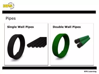
Pipe Material • Material selection influences pipe size • Nominal pipe size may be the same but different inside diameter (free area) • Influencing the friction loss and velocity
Copper has the more restrictive ID Nominal 2” Copper ID=1.985” Nominal 2” Steel ID=2.067”
Typical Procedure Size pipe based on: • Constant Friction Rate • Velocity • Use rule of thumb or common values
Constant Friction Rate • Range: 1’/100’ - 4’/100’ • 2.5’/100’ used on average (ASHRAE Fundamentals 2009 Chpt 22) • 4’/100’ when > 2” pipe diameter
Velocity • Define a maximum (Common: 4 fps ≤ 2”, 8 fps > 2”) • Limited primarily for noise & erosion • Higher values acceptable when air is removed from system • ASHRAE Fundamentals 2009 Chapter 22
Velocity - Material Impact Maximum velocity per Copper Tube Handbook* • Chilled Water 8 fps • Hot Water (<140ºF) 5 fps • Hot water (>140ºF) 3 fps ≤ ½” diameter pipe, lower velocities should be used due to craftsmanship and abrupt changes in flow direction Higher velocities acceptable in chilled water because the air is more easily removed than in hot water. *Copper Development Association
Commercial Steel Pipe (schedule 40) • ASHRAE Fundamentals 2009 Chapter 22 Figure 4
Commercial Steel Pipe (schedule 40) • ASHRAE Fundamentals 2009 Chapter 22 Figure 4 2.5’/100’ hd loss
Commercial Steel Pipe (schedule 40) • ASHRAE Fundamentals 2009 Chapter 22 Figure 4 2.5’/100’ hd loss 4’/100’ hd loss
Commercial Steel Pipe (schedule 40) • ASHRAE Fundamentals 2009 chapter 22 Figure 4 2.5’/100’ hd loss 4’/100’ hd loss 4 fps
Commercial Steel Pipe (schedule 40) • ASHRAE Fundamentals 2009 chapter 22 Figure 4 2.5’/100’ hd loss 4’/100’ hd loss 4 fps
Copper Tubing (Types K, L, M) • ASHRAE Fundamentals 2009 chapter 22 Figure 5 2.5’/100’ hd loss 4’/100’ hd loss 4 fps
Material Comparison Copper Steel
Noise • Noise velocity limits are difficult to pin point as it is dependent on many variables: • Insulation • Number of turns, fittings, valves • Air quantity • Partial flow • Typically not a significant concern as long as entrained air has been eliminated from a closed loop system.
Erosion • Velocities < 10 fps – erosion is not significant as long as there is no cavitation • ASHRAE Fundamentals 2009 Chapter 22
Aging • Build up and increased roughness occurs in pipe over time • Narrow the pipe free area increasing head • Often ignored • Unpredictable • Research data is not available • A greater concern for open systems
Example • 4 Story Office Building • Located in Houston, Texas • HVAC system: Fan Coil Units with Chilled Water coils
Zoning 2 3 1 4 5 6 Basement Mechanical Room
Zoning 1 2 3 4 5 6 8 7 11 9 10 Main Floor 13 12
Zoning 3 2 1 4 7 6 5 9 8 2nd/3rd Floor 10 11
Riser Steel Schedule 40 2.5’/100’ Copper 2.5’/100’ 3RD 23.7 GPM 2”, 2” 22.3 GPM 2”, 2” 2ND 46 GPM 2½”, 2½” 24.3 GPM 2”, 2” MAIN 70.3 GPM 3”, 3” 10.7 GPM 1¼”, 1¼” BASE 81 GPM 3”, 3”
Steel Schedule 40 2.5’/100’ Copper 2.5’/100’ Example Fan Coil Unit 0-3 (2.2) 0-2 (2.2) ¾”, 1” 1¼”, 1¼” 0-1 (0.9) 1”, 1” ½”, ½” 0-4 (1.7) 0-5 (1.7) 1¼”, 1¼” 0-6 (1.1) 3”, 3” co Basement 3”, 3” MECH ROOM (0.8)
Steel Schedule 40 2.5’/100’ Copper 2.5’/100’ Example 1-1 (1.5) 1-2 (0.95) 1-3 (0.8) Fan Coil Unit 1-4 (1.6) 1¼”, 1¼” 1”, 1” 1-5 (1.9) 1¼”, 1¼” 1-8 (1.9) 1 ¼”, 1 ½” 1-7 (2.0) 1-11 (1.4) 1½”, 1½” 1-10 (1.0) 1-9 (2.0) 2”, 2” co Main Floor 1-12 (3.7) 1-13 (4.9)
Steel Schedule 40 2.5’/100’ Copper 2.5’/100’ Example 2-2 (2.1) 2-3 (1.2) Fan Coil Unit 2-4 (2.0) 1”, 1” 2-7 (1.5) 1¼”, 1¼” 1¼”, 1¼” 2-1 (1.6) 2-6 (1.3) 2-5 (3.0) 2-9 (2.6) 1¼”, 1½” 1½”, 2” 2-8 (3.0) co 2nd Floor 2-11 (2.2) 2-10 (1.9) 2”, 2”
Steel Schedule 40 2.5’/100’ Copper 2.5’/100’ Example 3-3 (1.3) 3-2 (2.2) Fan Coil Unit 3-4 (2.1) 3-7 (1.6) 1”, 1” 1¼”, 1½” 3-1 (2.2) 3-5 (3.0) 3-6 (1.4) 1½”, 1½” 3-9 (2.8) 3-8 (3.1) 2”, 1½” 3rd Floor 3-11 (2.2) 3-10 (1.9) 2”, 2”
Riser Steel Schedule 40 2.5’/100’ 4’/100’ 4fps(≤2”); 8fps(>2”) 23.7 GPM 2”, 2”,1½” 3RD 22.3 GPM 2”, 1½”,1 ½” 2ND 46 GPM 2½”, 2½”,2½” 24.3 GPM2”, 2”,1 ½” MAIN 70.3 GPM 3”, 2½”,2½” 10.7 GPM 1¼”, 1¼”,1” BASE 81 GPM 3”, 3”,2½”
Example Steel Schedule 40 2.5’/100’ 4’/100’ 4fps(≤2”); 8fps(>2”) ¾”, ¾”, ¾” 0-2 (2.2) 0-3 (2.2) 1 ¼”, 1”,1” 0-1 (0.9) 1” 1” ¾” ½” ½” ½” 0-4 (1.7) 0-5 (1.7) 1¼”, 1¼”,1” 0-6 (1.1) 3” 3” 2½” 2½” 2½” 2½” co Basement MECH ROOM (0.8)
Example Steel Schedule 40 2.5’/100’ 4’/100’ 4fps(≤2”); 8fps(>2”) 1-3 (0.8) 1-1 (1.5) 1-2 (0.95) 1¼” 1” 1” 1-4 (1.6) 1¼” 1” 1” 1” ¾” ½” 1-5 (1.9) 1-8 (1.9) 1¼”, 1¼”, 1¼” 1-7 (2.0) 1-11 (1.4) 1½”, 1¼”, 1¼” 1-10 (1.0) 1-9 (2.0) co MainFloor 1-12 (3.7) 1-13 (4.9) 2” 2” 1½”
Example Steel Schedule 40 2.5’/100’ 4’/100’ 4fps(≤2”); 8fps(>2”) 2-3 (1.2) 2-2 (2.1) 2-4 (2.0) 1”, ¾”,½” 2-7 (1.5) 1¼”, 1¼”, 1” 1¼”, 1¼”, 1¼” 2-1 (1.6) 2-5 (3.0) 2-6 (1.3) 2-9 (2.6) 1¼”, 1¼”, 1” 1½”, 1½”, 1½” 2-8 (3.0) co 2nd Floor 2-11 (2.2) 2-10 (1.9) 2”, 1½”, 1½”
Example Steel Schedule 40 2.5’/100’ 4’/100’ 4fps(≤2”); 8fps(>2”) 3-2 (2.2) 3-3 (1.3) 3-4 (2.1) 3-7 (1.6) 1”, 1”, 1” 1¼”, 1¼”, 1” 1½” 1¼” 1¼” 3-1 (2.2) 3-5 (3.0) 3-6 (1.4) 3-9 (2.8) 3-8 (3.1) 2”, 1½”, 1½” 3rd Floor 3-11 (2.2) 3-10 (1.9) 2”, 2”, 1½”
Pump Energy Costs • Pressure drop (head) • Hours of operation • Annual flow profile • Pump control: constant vs variable pump flow • Energy rates • Efficiency of the pump
Pressure Drop • Energy must exerted to overcome resistance seen by the critical circuit • Poor hydronic system design and pipe lay out influences energy consumed • Items that impose resistance: • Valves • Coils • Fittings • Pipe Manufacturer Literature ASHRAE Tables
Pipe Resistance • Based on pipe size, flow, and material, length Example: 3” Schedule 40 pipe with 80 GPM, 50’ long 1.5’ of Head/100’ of pipe length 50’ of pipe X1.5’/100’ = 0.75’ Hd 1.5’/100’ • ASHRAE Fundamentals 2009 Chapter 22 Figure 4
Fitting Resistance • Based on pipe size and velocity ASHRAE Fundamentals 2009 Chapter 22
Pipe Resistance • Based on pipe size, flow, and material, length Example: 3” Schedule 40 pipe with 81 GPM 3.3 fps Velocity = 3.3 fps • ASHRAE Fundamentals 2009 Chapter 22 Figure 4
Fitting Resistance • Based on pipe size and velocity • ASHRAE Fundamentals 2009 Chapter 22 90⁰ Elbow Resistance = 8.1’ of straight pipe
Fitting Resistance • ASHRAE Fundamentals 2009 Chapter 22
Fitting Resistance • Based on pipe size and velocity Example: 3.5 FPS, 3” Steel pipe 45⁰ Elbow Multiply by the 0.7 correction value Resistance = 8.1’ x 0.7 5.7’ of straight pipe
Pressure Drop Calculation • The calculation is cumbersome and time consuming • Often simplified • Sized pipe using 2.5’/100’, apply this value to the total pipe length of critical circuit • Much of the pipe likely to operate at less than 2.5’/100’ at full load as in example • More common to multiply value by a factor such as 1.5 • Result: Over estimated head
ASHRAE Standard 90.1-2010 Prescriptive Path requirements Section 6.5.4.5 – Hydronic Systems and Control
ASHRAE Standard 90.1-2010 • Example: Schedule 40 pipe with 81 GPM • → 3” pipe using traditional sizing methods