Download
1 / 103
1.03k likes | 1.18k Vues
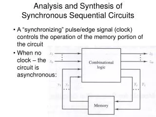
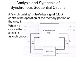
Application of Feynman-like notation to synthesis of circuits from memristors. Marek Perkowski. November 5, 2012. Using the Memristor to build basic logic gates. Logic Design with Memristors. Wiliams Team at HP Basic concepts Demonstration of IMPLY Demonstration of NAND

E N D
Application of Feynman-like notation to synthesis of circuits from memristors MarekPerkowski November 5, 2012
Logic Design with Memristors • Wiliams Team at HP • Basic concepts • Demonstration of IMPLY • Demonstration of NAND • Israeli Team at Technion - Kvatinsky • Circuit design methodology • Performance robustness tradeoff • Demonstration that the widely used memristor model is not pracrtical • Finnish team - Lehtonen • Show theory with minimum ancilla bits • No algorithm • No results • Restriction of assumption • Our work at PSU • Practical model • Practical assumptions • More generalOptimal algorithm
Leon Chua Historic Discovery • Leon Chua, The Missing Circuit Element, IEEE Proc. 1971. Invention based on search for general principles of physics and Nature = he referst to Aristotle etc
Memristors becoming practical R off = high resistance R ON = low resistance • Hewlett Packard 2008 • D Strukov et al The Missing Memristor found, Nature 2008 Very simplified model of memristor
So far, most of the applications of memristor are in analog design • Dr. Teuscher PSU – evolving CAM circuits • Memory Digital • Memory analog • Fuzzy Circuits • Analog Circuit • Neuromorphic Systems
Y. Ho et al, Nonvolatile Memristor Memory, Device Characteristics and Design Implications, ICCAD, 2009 A. Afifi et al, Implementation of Biologically Plausible Spiking Neural Network Models on the Memristor Crossbar-based CMOS/Nano Circuits.ECCTD 2009
We can do standard binary logic with memristors! • Logic values represented as resistances. • RON = logic 1, ROFF = logic 0. • Circuit uses primarily resistors • Memristor can be used as: • Input storage/processing • Output storage/processing • Computational logic element • Latch or memory circuit
Computing with Memristive Devices • Memristive Devices allow for reconfigurable logic • Will allow for reconfigurable analog circuis • They allow high density logic • They will be used in high density DSP and image processing, Neural, etc. applications. • Memristive devices will change computing paradigm. • CPU embedded memory • Reboot-less power down at any time • Extending Moore’s Law beyond CMOS Limit. • J Borghetti et al PNAS, Vol 106, No 6, 2009.
Islands of Memristors for parallel calculations, SIMD mode inside normal MOSFET logic
MemristiveStateful Logic Gate • This gate realizes material implication p q • Device q can be SET conditionally depending on the status of the device p. • “Stateful Logic”, functioning complete NAND and status storing in device s Needs two pulses Needs three pulses
Memristive Implication Logic • DR Stewart, GS Snider, PJ Kuekes, JJ Yang, DR Stewart, RS Williams, Nature 464, 873 (2010)
Memristive Implication Logic • DR Stewart, GS Snider, PJ Kuekes, JJ Yang, DR Stewart, RS Williams, Nature 464, 873 (2010) Needs two pulses
New value Set to 0 Pq 0 0 0 0 0 0 1
Memristor Based XOR gate Input and output data are in memristors • First create VRST by S1=1, S2 =0 • Next create VSET by S1=0, S2=1 • 2 memristors • 3 FETs • 1 resistor • 2 steps output
R Y R P R Q
In this approach, the logic state is represented as resistance, where a high resistance is logical state zero, and a low resistance is logical state one. • An example of this approach, the IMPLY logic gate, is shown in Figure 2.
Using the Memristor to build basic logic gates • NOT • OR • AND • NAND • NOR • EXOR • MUX • Memristor A x B
Costs of gates with memristors CHANGE Good for TANT, Negative gate methods
examples • ((abc)’+ (ab))’ + (bcd) = • ((a’ + b’ + c’) + ab)’ + bcd = • (abc) * (ab)’ + bcd = • (abc) * (a’ + b’) + bcd = • (b’c) + bcd
example • ((ab) 0) = (a’+b’) • ((ab) (ab)) = (a’+b’) + ab • (0 ab) = (ab) • (a b) = (a’+b)
All these circuits assume that value of b already exists. If it does not exist, we need two inverters (from IMPLY) to create it. a a + b b a a a + b 0 b a ( a + b) = a* b b 0 a b a + b = (a * b) 0
All these circuits assume that value of b already exists. If it does not exist, we need two inverters (from IMPLY) to create it. a a + b b a a a + b 0 b a ( a + b) = a* b b 0 a b 0 0 (a * b)
Now we assume that all inputs must be created with Stateful IMPLY technology from scratch.
NOT & OR NOT OR with two inputs A x A x B A A x x 0 0 B B 0 0
A x A x NOT 0 A B C A 0 NOT is a one WM gate
2-input OR A X=A+B 0 B B 0 0 B A B 2-input OR is a two WM gate B A+B 0 0 0 A B 0
NAND & AND NAND & AND
NAND & AND NAND & AND NAND A x B A 0 x B
NAND & AND A B C 0 0 NAND(a,b) 0 0 2-input NAND is a one ancilla gate 2-input AND is a two ancilla gate AND(a,b)
(c(ba) c) = (c’+(b’+a)=(bc)’+a Working (memorizing) memristor NAND(b,c,d) (yzv)’ + 0 bcd+yzv (ba) =b’+a (bcd)’+0 2 0 0 1 SOP b y NAND(y,z,v) Two Working Memristors c z Imply serves as inverter 2 v d 0 1 Realization of a Sum of positive Products
Inhibit gate A * B’ = (A’ + B)’ 2 gates 2-input INHIBIT is a two WM gate A B C Two working bits A’ + B A’ 0 A * B’ = (A’ + B)’ 0 0 B’
A B C 0 A (AB)’ 0 X=(AB)’C 0 (AB) (AB) + C’ 0 PS is a two WM gate
PSE gate has 2 WM X= (A+B+C) X A B A D C E B F C D E F C 0 0 0 0 X’+D’+E’+F’=(XDEF)’ B A XDEF 0 0 (A+B+C)=X
NOR is a two WM bit gate NOR A B C B (A+B)’ A 0 0 0 0 A+B A
EXOR = 8 literals in NAND = 8 IMPLY A B B’ A’ 0 0 A + B’ A B B + A’ 0 0 A’B 0 A’B + A B’ B EXOR is a three WM gate A’ A B’
SYNTHESIS WITH EXORS WITH NO LIMIT ON NUMBER OF ANCILLA BITS
First Working Memristor A Second Working Memristor C B Third Working Memristor A’ A’ 0 0 B’ B’ 0 0 A + B’ A + B’ A A B B B + A’ B + A’ 0 0 0 0 A’B A’B This circuit has 4 working memristors and 16 IMPLY gates 0 0 A’B + A B’ A’B + A B’ Fourth Working Memristor
A B B’ A’ 0 0 A + B’ A B B + A’ 0 0 A’B 0 A’B + A B’
A MUX B C AB + A’C A’ 0 0 A 0 (A’C)’ 0 (AB)’ (A+C’)’ MUX is a three ancilla gate B A C A’ 7 WM expected
Circuits from reversible gates versus circuits from memristor material implications Similarities Differences No inverter Different gates • No fanout • In-gate memory exists