Download
1 / 17
170 likes | 279 Vues
3D Model for Atomic Sputtering of Heterogeneous Ceramic Compounds. Aaron M. Schinder, Prof. Mitchell Walker, Prof. Julian Rimoli High-Power Electric Propulsion Lab Georgia Institute of Technology . 10 July 2013. 49th AIAA/ASME/SAE/ASEE Joint Propulsion Conference & Exhibit . Motivation.

E N D
3D Model for Atomic Sputtering of Heterogeneous Ceramic Compounds Aaron M. Schinder, Prof. Mitchell Walker, Prof. Julian Rimoli High-Power Electric Propulsion Lab Georgia Institute of Technology 10 July 2013 49th AIAA/ASME/SAE/ASEE Joint Propulsion Conference & Exhibit
Motivation Ion Trajectories • Hall effect thrusters (HETs) are attractive for spacecraft propulsion and station-keeping • Operating life of HETs is limited by erosion of the discharge channel wall • Accelerated plasma erodes the channel wall where it impacts the surface • The discharge channel erodes, exposing magnetic circuit • Sputtering of magnetic circuit can lead to ferrous deposition, destroying electrical isolation and leading to unexpected failure • Cost of life tests is substantial • Life models reduce risk of life tests • Ability to predict life with conditions not addressed during life test Diagram of HET channel wall erosion process
Motivation • Complex 3D surface structures develop in long-duration life testing of HETs Left: BPT-4000 thruster, 10,400 hour life test, showing azimuthal saw-tooth erosion not captured in present modeling Right: Eroded SPT-100 thruster de Grys. Mathers. Welander., “Demonstration of 10,400 Hours of Operation on a 4.5 kW Qualification Model Hall Thruster,” AIAA Joint Propulsion Conference, 2010-6698 M. Dudeck, F. Doviel, et. al “Plasma Propulsion for Geostationary Satellites and Interplanetary Spacecraft”. 15th International Conference on Plasma Physics and Applications, 1–4 July 2010, Iasi, Romania
Motivation • Present erosion models model the material as a homogenous isotropic solid: No material driven process for formation of surface structure • Sparse experimental sputtering yield data for energies less than ~200 eV: Hall thruster ions have energies in the range of 100-300 eV • Present erosion models use an axisymmetric plasma model, such as HPHall, and do not produce information about 3D erosion features, or the 3D nature of microscopic surface roughness • In order to model the interaction of sputtering with the material microstructure, a 3D model of sputtering of a heterogeneous material is produced
3D Heterogeneous Model: Introduction • To model the interaction of sputtering with the material microstructure, a 3D model of sputtering of a heterogeneous material is produced Ray-tracing approach to heterogeneous atomic sputtering model
Empirical Background for Model Ion Trajectories • AFRL/UM P5 Channel Wall • Material: M26 BN-SiO2 composite (60% BN/40% SiO2 by mass) • Most HETs use M26, machinability • SEM Imaging (surface and cross section) • XPS Imaging (surface composition) • LEXT Profilometry (surface. • Regions of Interest: • Non Eroded • Lightly Eroded • Highly Eroded (beyond acceleration zone) Diagram of HET channel wall erosion process SEM cross sectional image of M26 BN-SiO2microstructure
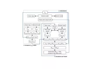
3D Heterogeneous Model: Overview • 2d surface mesh is propagated into 3d model domain • 1st order plasma model and single ion beams are used to model plasma conditions • Plasma model: displaced Gaussian velocity distribution fit to Ion Energy Distribution data • Ray-tracing is used to calculate shadowing of material from each ion beam Erosion model flowchart
3D Heterogeneous Model: Component Models • BN and HBC phases were modeled with curve fits from Yalin et. al’s QCM sputtering yield experiments on HBC and quartz Component model curve-fitting coefficients Component model curve fits and data, 45° Yalin, A. P., Rubin, B., Domingue, S. R., Glueckert, Z., and Williams, J. D., "Differential Sputter Yields of Boron Nitride, Quartz, and Kapton Due to Low Energy Xe+ Bombardment," AIAA Paper 2007-5314, July 2007
3D Heterogeneous Model: Material Domain Models • Large and small scale domain models focus on different features of material domain Small scale domain model Focus: Individual BN flakes Large scale domain model Focus: Silica voids and BN rich regions Large scale structure, roughness SEM cross sectional image of M26 BN-SiO2microstructure
Results: Deviation from Law of Mixtures • Model was validated for convergence of average erosion rate • Model was validated by varying mixture fraction • Result: Surface structure produces deviation from law of mixtures • Effect of shadowing, surface features • Avg. Erosion rate biased towards lower yield component Average and one standard deviation of erosion rate as a function of mixture fraction
Results: Qualitative Surface Features • Conditions for figures: 750 s, 30º ion incidence, 3*1017 m-3Xe • Reproduction of cliff and valley structures • BN rich regions shadow higher yield silica material behind them • Surface roughness results. Features highly sensitive to ion incidence angle • Moderate incidence angles of ~30° correspond to observed features a) Simulated erosion profile, b) SEM image of highly eroded section of channel wall a) Surface height profile of P5 channel wall b) Simulated profile, 30º incidence, 750 s, 3E17 m-3
Results: Quantitative Roughness for Moderate Incidence Angles • Ion incidence angle was varied to produce profiles with different features and surface roughness characteristics • The 30° ion incidence case has the closest roughness to experiment: 8 µm compared to 6 ± 2.5 µm • For my longest time-scale runs, rms roughness remains bounded. Peak-to-valley distance continues to increase Top: Rms roughness as a function of erosion depth, angle series Bottom: Rms, peak-to-valley roughness, long-time-scale simulation
Results: Composition of Surface • Composition of the P5 channel wall was measured via X-ray photoelectron spectroscopy (XPS) • Experimentally, a reduction in BN in the highly eroded region of the P5 thruster was found. BN is the lowest-yield phase, and was expected to persist relative to silica • This result is corroborated by Garnier’s XPS of M26 pre and post exposure to an ion beam • The simulation shows no significant variation in simulated surface composition. (A slight increase of 10% with no coherent trend afterwards) Top: Empirical measurements of composition pre and post plasma exposure Bottom: Simulated variation in surface composition with erosion depth
Results: Composition of Surface • A purely atomic sputtering approach to erosion cannot capture the observed variation in surface composition • Simplified analytical model: • As plane moves into regular domain, no variation in surface composition results: Similar but translated images of initial surface:
Results: Composition of Surface • Grain ejection model: • If BN grains protrude from a silica matrix to the point where a critically small support is obtained, they are detached and ejected from the material • This model can explain an increase in silica in material that has been eroded. • Subject of future work
Conclusions • Shadowing introduces deviation from a simple law of mixtures wrt. erosion • Qualitative surface features reproduced for moderate, but not shallow ion incidence angles. Cliff and valley structure reproduced • Surface roughness reproduced for moderate ion incidence angles: 8 µm simulated, 6±2.5 µm observed • Observed composition not reproduced in atomic sputtering model. Grain ejection model is presented as plausible mechanism for composition changes, to be investigated in future work