Download
1 / 20
220 likes | 455 Vues
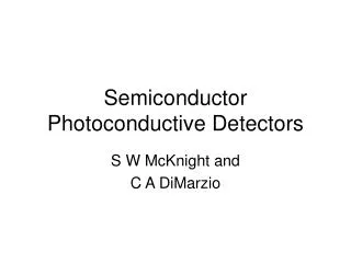
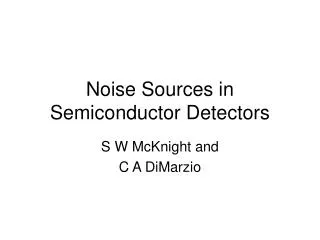
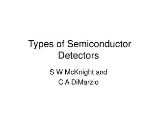
Room Temperature Semiconductor Detectors. Room Temperature Semiconductor Detectors. Tutorial Presented at Alabama A&M University Lodewijk van den Berg Constellation Technology Corporation With the cooperation of Alexsey Bolotnikov Brookhaven National Institute Laboratory

E N D
Room Temperature Semiconductor Detectors Tutorial Presented at Alabama A&M University Lodewijk van den Berg Constellation Technology Corporation With the cooperation of Alexsey Bolotnikov Brookhaven National Institute Laboratory Normal, AL, Thursday 13 July, 2006
Room Temperature Semiconductor Detectors • What are semiconductor Detectors, and what are the Requirements? • Solid semiconductor material • Chemically stable and preferably inert to atmospheric conditions • Able to absorb high energy nuclear radiation without being destroyed • Able to convert absorbed radiation photons into electronic charges of • The amount of electronic charges created should be a linear function of the • energy of the radiation • Should have high quality single crystalline structure • Should have very small levels of impurities ( < 10 ppm total)
Principles of Operation • A piece of semiconductor material is cut to the desired dimensions and • electrodes are deposited on opposite sides. • The electrode material is usually a noble metal, e.g. Au, Pd, Pt, Ag, but • sometimes common metals and conductive organic polymers are used. • Contact wires are attached to the electrodes to connect the detector to a • high voltage power supply on one side and a signal processing system on • the other side. • The charges created by the radiation are driven by the bias toward the • electrodes and are counted and processed by the electronic system. • Charges may not be able to travel the whole distance from their point of • origin to the respective electrodes because of trapping at material defects.
Charge Transport Properties • The movement of the electronic charges to the contacts can be described by • the mobility and the trapping time (also called lifetime). • The mobility µ with dimensions cm2/Vs (or cm/sec per V/cm) determines the • velocity with which the charge moves in the lattice under the force of the • field E applied to the detector. • The trapping time in seconds represents the probability that a charge is • trapped at a crystalline defect during the time that the charge travels through • the detector. • The drift length (cm) = E is the average distance a charge can travel • before it is trapped.
Charge Transport and Collection • The collection of charges is described in the most extensive way by the • Hecht equation, which considers all the possible trapping mechanisms. • Basically it can be expressed for one type of charge (electrons or holes) : • Q = Q0 x e–d/ • where Q is the amount of charge collected, • Q0 is the amount of charge generated • d is the thickness of the detector. • One can see from the equation that in order to collect 98 % of the charges • generated, the value of the drift length should be > 5d. • This condition is often difficult to meet in semiconductor detectors; • therefore values of > 2d are often accepted.
Fast Pickoff Daughterboard Gate Generator Gate HV Filter Hg I2 Detector HV Gain Preamplifier Energy Shaping Amp Gated Integrator Charge Collection and Analysis System Counts Multi Channel Analyzer (MCA) Channels (Energy)
Charge Collection and Analysis System (continued) • The schematic on the previous page shows the following features: • The high voltage applied to the detector makes the charges generated by the • absorbed radiation move to the respective electrodes. • The side of the detector from which the signal is taken is in most cases held at • a neutral bias. • Charges which are collected at the opposite electrode create an image charge • on the signal electrode, so that essentially all charges are accounted for. • The charge pulse (current) is processed by the preamplifier containing a Field • Effect Transistor (FET) which removes a large part of the continuous current • flowing through the preamplifier and highlights the signal.
Charge Collection and Analysis System (continued) • The charges enter the shaping amplifier which amplifies the current and also • determines the time (in microseconds) during which charges will be collected. • The charges from the shaping amplifier are processed by the Multi-Channel • Analyzer. The MCA reads the amount of charge in the pulse delivered by the • shaping amplifier. It sets up a number of bins (or channels) over which it • distributes the number of times a certain charge is received. • This information can be displayed on a PC and is called a spectrum. • Ideally the spectrum of a monochromatic test source should be a sharp peak • distributed over a few channels. The broadening of the peak is caused by • incomplete charge collection, Compton scattering and other effects in the • crystal which cause charges to be lost or not generated.
Materials • Many materials have been investigated in the past. In the following table a • selection is made using criteria which will help to focus this discussion. • High density of a material improves the absorption of the radiation. • The type of interaction needs to be considered. Materials containing high Z • element(s) have a higher full-energy peak efficiency. This means that the • energy of the radiation is more efficiently converted into the maximum • number of counts possible. This relationship is related to Z3. • Higher Z materials also have lower Compton Scattering, which is a loss of • energy of the absorbed radiation photon by means of elastic scattering. • Materials with a small electronic band-gap have low resistivity. This causes • a high leakage current and a noisy spectrum when bias is applied
Comments on Materials Table • The resistivities for the different materials given in the previous table have • been calculated on the basis of their measured band gap. • In reality, the actual crystals grown contain many defects which usually • lowers the resistivity by as much as two or three orders of magnitude. • The standard for all nuclear research and measurements is still LN2 • cooled high purity Ge (HPGE), but cooling is not readily available • for field applications. • The only two solid state detector materials presently available for ambient • temperature applications are CdZnTe and HgI2 . • This discussion will continue with the description of some properties and • applications of CZT. A separate presentation will discuss HgI2.
Room Temperature DetectorsCZT • Review of CZT Properties • Resistivity after doping 1010 Ohm.cm • Electron Mobility 1350 cm2/Vsec • Hole Mobility 120 cm2/Vsec • Electron Mu-Tau 1x10⁻³ cm2/V • Hole Mu-Tau 6x10⁻⁶ cm2/V • Crystal can be grown in large sizes (2 inch diameter and 10 inches long or • larger), but contain inclusions and segregations. • The low values of the mu-tau for holes makes it impossible to make planar • detectors with large thicknesses.
Apparent bulk resistivity Room Temperature DetectorsCZT Bulk Leakage Currents(Brookhaven National Laboratory) measurements of bulk resistivity values ~1010 Ohm.cm ~V1/2 Fitting results: 3x10⁹ Ohm-cm – Imarad 5x10¹⁰ Ohm-cm – eV-Products 3x10¹⁰ Ohm-cm – Yinnel Tech
Room Temperature DetectorsCZT • The low mu-tau product of the holes in CZT combined with the relatively low • resistivity makes it impossible to make planar detectors. Thicker detectors can • be used by using single charge collection of the electrons only. Three detector • configurations have been developed to make this possible. • Coplanar Grid detectors, where the anode is formed by two interwoven anode • grids. One grid serves as the signal anode, and the other is a steering grid used • to drive the electrons to the anode grid. (P. Luke at U.C. Berkeley) • Pixellated anodes where each pixel is connected to analysis channel of a • CMOS based ASIC. (Zhong He and coworkers at Univ. of Michigan) • Frish Grid detectors where the long narrow body of the detector is wrapped • in a teflon/conductor as the cathode. ( McGregor, KSU, and Bolotnikov, BNL)
Room Temperature DetectorsCZTCo-planar Grid Detectors The bottom of the detector has a solid contact and is the cathode. The top has two parallel grids; one serves the anode and the other as a steering grid. Dimensions of the detector: 1 cm x 1 cm x 1 cm.
Room Temperature DetectorsCZTPixellated Detector The back of the detector is a solid cathode contact. The front has an array of small pixel contacts as sketched in the lower figure. The anode pixels are connected to an ASIC as shown. Dimensions of the detector: 1 cm x 1 cm x 7 mm.
Room Temperature DetectorsCZTFrisch Grid Detectors The top figure shows the bare detector. The bottom figure shows the teflon wrap and the conductive shield which acts as the cathode. The top surface has the anode contact. Dimensions of the detectors: 6 mm x 6 mm x 3 mm up to 15 mm x 10 mm x 10 mm.
Room Temperature DetectorsCZTCs-137 Spectrum (BNL) Spectrum of Cs-137 with detector 5 mm thick. Resolution 1.1% FWHM. Single charge collection. Energy resolution: 1.1% (Frisch-ring) vs. 0.9% (3D device) Resolution is limited by material non-uniformities!
Room Temperature Semiconductor DetectorsCZT and HgI2 • Summary • Room temperature semiconductor detectors are able to provide nuclear • spectra with a resolution adequate for many applications. • Since they are solid state devices, they are very rugged and are suitable for • devices used in the field (no glass components). • The signal output is stable with temperature and does not drift. • Improvements in the material are needed, especially in the crystal growth. • Specifically, the single crystal material needs to be more homogeneous with • respect to its electronic properties, and segregation and inclusions need to be • minimized. In this way, detector bodies with larger volumes will become • available, so that efficiency can be maximized.