Download
1 / 80
1.19k likes | 2.07k Vues
Chapter 3: Signals Analog and Digital Signals. To be transmitted, data must be transformed to electromagnetic signals . Analog and Digital. Analog and Digital Data Analog and Digital Signals Periodic and Aperiodic Signal. Data. Data can be Analog infinite number of values in a range

E N D
Chapter 3: SignalsAnalog and Digital Signals To be transmitted, data must be transformed to electromagnetic signals.
Analog and Digital • Analog and Digital Data • Analog and Digital Signals • Periodic and Aperiodic Signal
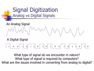
Data • Data can be • Analog • infinite number of values in a range • Digital • limited number of defined values
Analog Signals • Sine wave : most fundamental form of a periodic analog signal • Amplitude • Absolute value of a signal’s highest intensity, Normally in volts • Frequency • number of periods in one second, inverse of period • Change in a short span of time means high frequency • Phase • Position of the waveform relative to time zero (degrees or radians )
Time and Frequency Domains • Time-domain plot • displays changes in signal amplitude with respect to time • Frequency-domain plot • compares time domain and frequency domain
Digital Signals • Use binary (0s and 1s) to encode information • Less affected by interference (noise) • Fewer errors • Describe digital signals by • Bit interval • time required to send one bit • Bit rate • number of bit intervals per sec (bps) • Analog bandwidth • range of frequencies a medium can pass (hertz) • Digital bandwidth • maximum bit rate that a medium can pass (bps)
Data Rate Limits • How to determine the maximum bit rate (bps) over a channel? • Data rate depends on 3 factors • Bandwidth available • Levels of signals we can use • Quality of the channel (level of noise) • Two theoretical formulas were developed to calculate the data rate • Nyquist for a noiseless channel • Shannon for noisy channel
Noiseless ChannelNyquist Bit Rate • Defines the theoretical maximum bit rate BitRate = 2 Bandwidth log2L L is the number of signal levels used to represent data Example Consider a noiseless channel with a bandwidth of 3000 Hz transmitting a signal with two signal levels. The maximum bit rate can be calculated as BitRate = 2 3000 log2 2 = 6000 bps
Noisy ChannelShannon Capacity • Determine the theoretical highest data rate for a noisy channel C = B log2 (1 + SNR) Example We can calculate the theoretical highest bit rate of a regular telephone line. A telephone line normally has a bandwidth of 3000 Hz (300 Hz to 3300 Hz). The signal-to-noise ratio is usually 3162. then Channel capacity = 3000 log2 (1 + 3162) = 3000 log2 (3163) = 3000 11.62 = 34,860 bps
Transmission Impairment • Imperfections cause impairment, which means that a signal at the beginning and the end of the medium are not the same • Three types of impairments 1) Attenuation • Loss of energy, Amplifiers are used to strengthen • To show that a signal has lost or gained strength, engineers use the concept of decibel (db) • The Decibel measures the relative strength of two signals or a signal at two different points Example A signal travels through a transmission medium and its power is reduced to half. This means that P2 = 1/2 P1. Calculate the attenuation (loss of power)? attenuation = 10 log10 (P2/P1) = 10 log10 (0.5P1/P1) = 10 log10 (0.5) = 10(–0.3) = –3 dB
2) Distortion • Signal changes form or shape • Each component has its own propagation speed, therefore its own delay in arriving 3) Noise • Thermal noise – random motion of electrons, creating an extra signal • Induced noise – outside sources such as motors and appliances • Crosstalk – effect of one wire on another • Impulse noise – a spike for a short period from power lines, lightning
Digital Transmission Ch4 • Methods to transmit data digitally • Line coding • Process of converting binary data to a digital signal • Block coding • Coding method to ensure synchronization and detection of errors • Three steps • Division • Substitution • Line coding • Sampling • is process of obtaining amplitudes of a signal at regular intervals • Transmission modes • Parallel • Serial • Synchronous • Asynchronous
Signal Level versus Data Level • Signal level • number of values allowed in a particular signal • Data level • number of values used to represent data • Note: figure b should say three signal levels, two data levels
Pulse Rate versus Bit Rate • Pulse • minimum amount of time required to transmit a symbol • Pulse rate • defines number of pulses per second • Bit rate • defines number of bits per second • BitRate = PulseRate x log2L • where L is the number of data levels A signal has four data levels with a pulse duration of 1 ms. We calculate the pulse rate and bit rate as follows: Pulse Rate = 1000 pulses/s Bit Rate = PulseRate x log2 L = 1000 x log2 4 = 2000 bps
Line Coding • Process of converting binary data to a digital signal • Line Coding schemes • Unipolar • Polar • Bipolar
Unipolar • Uses only one voltage level • Polarity is usually assigned to binary 1; a 0 is represented by zero voltage • Potential problems: • DC component • Lack of synchronization
Polar • Uses two voltage levels, one positive and one negative • Alleviates DC component • Variations • Nonreturn to zero (NRZ) • Return to zero (RZ) • Manchester • Differential Manchester
Polar • NRZ • Value of signal is always positive or negative • NRZ-L • Signal level depends on bit represented • positive usually means 0 • negative usually means 1 • Problem: synchronization of long streams of 0s or 1s • NRZ-I (NRZ-Invert) • Inversion of voltage represents a 1 bit • 0 bit represented by no change • Allows for synchronization • Long strings of 0s may still be a problem
Return to Zero (RZ) • May include synchronization as part of the signal for both 1s and 0s • How? • Must include a signal change during each bit • Uses three values: positive, negative, and zero • 1 bit represented by pos-to-zero • 0 bit represented by neg-to-zero • Disadvantage • Requires two signal changes to encode each bit; more bandwidth necessary
Manchester • Uses an inversion at the middle of each bit interval for both synchronization and bit representation • Negative-to-positive represents binary 1 • Positive-to-negative represents binary 0 • Achieves same level of synchronization with only 2 levels of amplitude
DifferentialManchester • Inversion at middle of bit interval is used for synch • Presence or absence of additional transition at beginning of interval identifies the bit • Transition 0; no transition1 • Requires two signal changes to represent binary 0; only one to represent 1
Bipolar Encoding • Uses 3 voltage levels: pos, neg, and zero • Zero level 0 • 1s are represented with alternating positive and negative voltages, even when not consecutive • Two schemes • Alternate mark inversion (AMI) • Bipolar n-zero substitution (BnZS)
Block Coding • Coding method to ensure synchronization and detection of errors • Three steps • Division • Substitution • Line coding
Sampling • Analog data must often be converted to digital format (ex: long-distance services, audio) • Sampling is process of obtaining amplitudes of a signal at regular intervals
Pulse Amplitude Modulation • Analog signal’s amplitude is sampled at regular intervals; result is a series of pulses based on the sampled data • Pulse Coded Modulation (PCM) is then used to make the signal digital
Pulse Coded Modulation • First quantizes PAM pulses; an integral value in a specific range to sampled instances is assigned • Each value is then translated to its 7-bit binary equivalent • Binary digits are transformed into a digital signal using line coding
Sampling Rate: Nyquist Theorem • Accuracy of digital reproduction of a signal depends on number of samples • Nyquist theorem • number of samples needed to adequately represent an analog signal is equal to twice the highest frequency of the original signal Example What sampling rate is needed for a signal with a bandwidth of 10,000 Hz (1000 to 11,000 Hz)? Each sample is 8 bits Solution The sampling rate must be twice the highest frequency in the signal Sampling rate = 2 x (11,000) = 22,000 samples/sec Bit rate = sampling rate x number of bits /sample = 22000 x 8 = 172 Kbps
4.4 Transmission Mode • Parallel • Bits in a group are sent simultaneously, each using a separate link • n wires are used to send n bits at one time • Advantage: speed • Disadvantage: cost; limited to short distances • Serial • Transmission of data one bit at a time using only one single link • Advantage: reduced cost • Disadvantage: requires conversion devices • Methods: • Asynchronous • Synchronous
Asynchronous Transmission • Slower, ideal for low-speed communication when gaps may occur during transmission (ex: keyboard) • Transfer of data with start and stop bits and a variable time interval between data units • Timing is unimportant • Start bit alerts receiver that new group of data is arriving • Stop bit alerts receiver that byte is finished • Synchronization achieved through start/stop bits with each byte received Requires additional overhead (start/stop bits) • Cheap and effective
Synchronous Transmission • Bit stream is combined into longer frames, possibly containing multiple bytes • Requires constant timing relationship • Any gaps between bursts are filled in with a special sequence of 0s and 1s indicating idle • Advantage: speed, no gaps or extra bits • Byte synchronization accomplished by data link layer
Chapter 6Multiplexing • Multiplexing • A set of techniques that allows the simultaneous transmission of multiple signals across a single data link • Can utilize higher capacity links without adding additional lines for each device – better utilization of bandwidth • Multiplexer (MUX) • Combines multiple streams into a single stream (many to one). • Demultiplexer (DEMUX) • Separates the stream back into its component transmission (one to many) and directs them to their correct lines.
TIME DIVISION MULTIPLEXING • Digital process that allows several connections to share the high bandwidth of a link • Time Slots and Frames • Each host given a slice of time (time slot) • A frame consists of one complete cycle of time slots, with one slot dedicated to each sending device.
TDM Frames • Mux-to-mux speed = aggregate terminal speeds • data rate of the link that carries data from n connections must be n times the data rate of a connection to guarantee the flow of data • i.e., the duration of a frame in a connection is n times the duration of a time slot in a frame
Example • Four 1-Kbps connections are multiplexed together. A unit is 1 bit. Find • the duration of 1 bit before multiplexing • the transmission rate of the link • the duration of a time slot, and • the duration of a frame? • Solution • The duration of 1 bit = 1/1 Kbps = (1 ms). • The rate of the link = 4 * 1 Kbps =4 Kbps. • Time slot duration = 1/4 ms = .25 ms • Frame duration = 4 * .25 ms = 1 ms.
INTERLEAVING • Process of taking a specific amount of data from each device in a regular order • May be done by bit, byte, or any other data unit • Character (byte) Interleaving • Multiplexing perform one/more character(s) or byte(s) at a time • Bit Interleaving • Multiplexing perform on one bit at a time
example • Four channels are multiplexed using TDM. If each channel sends 100 bytes/s and we multiplex 1 byte/ channel • show the size of the frame • Frame rate • Duration of a frame • Bit rate for the link.
Example • A multiplexer combines four 100-Kbps channels using a time slot of 2 bits. • Show the output with four arbitrary inputs. • What is the frame rate? 400 Kbps/8 = 50K frame/sec • What is the frame duration? (1/50K) = .02 ms = 20 µs • What is the bit rate? 4 * 100kbps = 400 Kbps • What is the bit duration? ( 1/400 K) = 2.5 µs
SYNCHRONIZING • Framing bit (s) is (are) added to each frame for synchronization between the MUX and DEMUX • synchronization bits allows the DEMUX to synchronize with the incoming stream so it can separate time slots accurately • If 1 framing bit per frame, framing bits are alternating between 0 and 1
Example We have four sources, each creating 250 char/ sec. If the interleaved unit is a character and 1 synchronizing bit is added to each frame, find (1) Data rate of each source 2000 bps = 2 Kbps (2) Duration of each character in each source 1/250 s = 4 ms (3) Frame rate link needs to send 250 frames/sec (4) Duration of each frame 1/250 s = 4 ms (5) Number of bits in each frame 4 x 8 + 1 = 33 bits (6) Data rate of the link. 250 x 33 = 8250 bps
Example • 2 channels, one with a bit rate of 100 Kbps and another with a bit rate of 200 Kbps, are to be multiplexed. • How this can be achieved? • What is the frame rate? • What is the frame duration? • What is the bit rate of the link? Solution • Allocate 1 slot to the 1st channel and 2 slots to the 2nd channel. • Each frame carries 3 bits. • The frame rate is 100k frames/sec because it carries 1 bit from the first channel. • The frame duration is 1/100,000s= 10 us. • The bit rate is 100,000 frames/s x 3 bits/frame= 300 Kbps
STDM • Mux-to-Mux speed < aggregate terminal/host speeds • Time slots allocated based on traffic patterns • uses statistics to determine allocation among users • must send port address with data (takes additional time slots) • May Potential loss of data during peak periods • may use data buffering and/or flow control to reduce loss • Not always transparent to user terminals and host/FEP • delays and data loss possible • So why use a stat mux? • more economical - need fewer muxes, cheaper lines • more efficient - allows more terminals to share same line • OK to use in many situations (e.g., terminal users
FREQUENCY DIVISION MULTIPLEXING • Assigns different analog frequencies to each connected device • Like Pure TDM, • mux-to-mux speed = aggregate terminal speeds • No loss of data so transparent to users and host/FEP • Channels must be separated by strips of unused B.W - guard B.W
FDM PORCESS • Signals of each channel are modulated onto different carrier signal • The resulting modulated signals are then combined into a single composite signal that is sent out over a media link • The link should have enough bandwidth to accommodate it
FDMDEMULTIPLEXING • Demultiplexer uses a series of filters to decompose the multiplexed signal into its constituent component signals • The individual signals are then passed to a demodulator that separates them from their carriers and passes them to the waiting receivers
Example • Assume that a voice channel occupies a B.W of 4 KHz. We need to combine 3 voice channels into a link with a B.W of 12 KHz, from 20 to 32 KHz. Show the configuration using the frequency domain without the use of guard bands Solution Shift (modulate) each of the 3 voice channels to a different B.W
Example • 5 channels, each with a 100-KHz B.W, are to be multiplexed together. What is the minimum B.W of the link if there is a need for a guard band of 10 KHz between the channels to prevent interference? Solution • For 5 channels, we need at least 4 guard bands. • the required B.W is at least 5 x 100 + 4 x 10 = 540 KHz
Wave Division Multiplexing • An analog multiplexing technique to combine optical signals • Multiple beams of light at different frequency • Carried by optical fibber • A form of FDM • Each color of light (wavelength) carries separate data channel • Commercial systems of 160 channels of 10 Gbps now available