Download
1 / 32
320 likes | 328 Vues
This presentation discusses the status of studies on the power circuit architecture and protection for the Future Circular Collider (FCC) at CERN. It explores different powering layout options, distribution of power flows, magnet design limitations, and proposes possible solutions for circuit protection. The presentation also introduces the concept of co-simulation using CLIQ for circuit and quench simulations.

E N D
Status of studies on FCC magnet circuit architecture and protection Marco Prioli CERN, TE-MPE FOR
Magnets parameters All numbers in this presentations are obtained for the following magnet versions Cos-theta v22b Block coil v20ar Common coil v1h2_1ac1 Canted cos-theta
Timeline April 2016 FCC week November 2016 ECC WP5 review May 2017 FCC week t 2 presentations about circuit protection • M. Prioli, “Concepts for magnet circuit powering and protection” (Link) • A. Verweij, “Comparison of magnet designs from a circuit protection point of view” (Link)
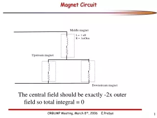
1 - FCC vs LHC powering layout PC 1 PC 1 PS 1 LHC FCC PS 1 PS 2 Sector 1 3km HalfArc 1 8km PC 2 20 PS in total In order to reduce the circuit inductance, the half arc of the FCC is subdivided in two powering sectors (PS) The total number of power converters (PC) is doubled
1 - Powering layout options A B D C Example for N=5 E
1 - FCC vs LHC ramp-up ~280 MW ~240 MW 14 MW • Maximum power to ramp-up dipole magnets in the whole accelerator • Independent of the circuit layout • MiniArcs included • Losses and inefficiency non included
1 - Distribution of maximum power flows tramp = 20 minconstant voltage tramp = 20 minconstant voltage + constant power Ramp-up of FCC block coil magnets only, MiniArcs included, net power (no losses and inefficiency)
1 - Conclusions • Possible directions for the layout of dipole circuits have been identified for the FCC • Subdivision of a 4 km long half-arc in several dipole circuits seems the most feasible solution for proper circuit protection within the required constraints, while at the same time having all converters and EE systems at the access points (using a SC link). • With the subdivision, the ramp-up is not challenging. Trade-off: • Peak power • Ramp-up time (Machine availability) • Decrease the power peak while preserving the same ramp-up time is possible
2 - Are there hard limits for the magnet design? A string of magnets can always be protected, for any magnet design and given constraints (voltage withstand level, tcirc, …), by adapting the number of circuits, so by subdividing a powering sector in multiple circuits. Example for N=5 Circuit protection, trade off: Number of circuits tcirc(busbar& diode size & quench prop.) VFPA,max Magnet powering, trade off:Number of circuits Converter voltage rating (VPC) Ramp time (tramp)
2 - Assuming 2x larger stored energy with same current • Same: • cable • circuit • ramp time • nrof EE systems (NEE) • VFPA,max More copper in cable Increase nr of circuits or number of EE systems High priority: Minimize stored energy
2 - Assuming 2x larger cable (half number of turns) with same stored energy • Same: • circuit • ramp time • nrof EE systems (NEE) • VFPA,max Not obvious what is preferable: Low-Inom& High-LM versus High-Inom & Low-LM
2 – Conclusion: how to reduce circuit complexity • Magnet designers should try to minimize the stored energy. Cos- and block designs have clear advantages as compared to the common-coil design. • High voltage withstand levels of the circuits and all its components are needed to reduce the number of circuits. • High-current low-inductance magnets are favourable in terms of quench voltage and number of circuits, which seem to outweigh the drawbacks • I suggest to design several cos- and block dipoles with the usual EuroCirCol requirements, but with Inom=15-25 kA. • The possibility of independent powering of the dipole apertures, each in series with a RQD/F circuit, should be explored from optics point-of-view. This might significantly reduce the number of busbars, power converters, DFB’s, and current leads.
Timeline April 2016 FCC week November 2016 ECC WP5 review May 2017 FCC week t 1 presentation about circuit protection and magnet protection (CLIQ) M. Prioli, “Circuit protection aspects, CLIQ simulations and STEAM” (Link)
3 - Outlook for circuit and quench simulations Lfilt M1 M2 M27 Cfilt PC REE Rfilt M54 M53 M28 Mn Example: magnets powered with Ncircuits per PS = 4 CLIQ • To understand if this proposal is feasible, circuit simulations are needed • Quenching magnet • CLIQ protection system • Lumped element model of the other magnets in the chain • Other components (e.g. Power Converter (PC), nonlinear switches) • … Quench protection system, controller of Power Converter • CLIQ introduces a coupling between circuit and quench simulations
3 - Field-circuit coupling Circuit model Cadence PSpice Lfilt CCLIQ M1 M2 M18 Cfilt Mn PC REE M Rfilt M35 M19 M36 L2 L1 R2 R1 ΔU2 ΔU1 φ, R 2D Electro-thermalField model I
3 - First CLIQ co-simulationCos-theta v22b CCLIQ=20 mF, UCLIQ=2 kV − − + + − − + + • Current [A] and resistance [Ω] evolution Coupling losses [W/m3]
3 - First CLIQ co-simulationCos-theta v22b CCLIQ=20 mF, UCLIQ=2 kV Hot-spot 312 K Peak voltage to ground @ 120ms • Temperature [K] Voltage to ground [V]
3 -Conclusion • A new tool for circuit and quench protection simulations • First fully consistent CLIQ simulations • Flexibility enables study of complex circuits/magnets without additional effort
Timeline April 2016 FCC week November 2016 ECC WP5 review May 2017 FCC week t 1 poster with the study of different CLIQ configurations to reduce the voltage to ground after a quench M. Prioli, “Strategies to reduce the voltage to ground in the FCC main dipole circuits” (Link)
4-Conclusion • Co-simulation has proven to be an effective approach for the study of the CLIQ protection system from the circuit and magnet points of view. • Co-simulation of LEDET and PSpice was validated against LEDET monolithic simulation. • The multi-CLIQ strategy is a promising option for the quench protection of the FCC block-coil dipole.
Proposal for next activities Circuit protection • Engage other actors in the circuit layout study • PCs point of view (Benjamin Todd, Valerie Montabonnet ?) • Availability point of view (Andrea ?) • Infrastructure and operation point of view (Volker Mertens ?) • Quadrupole powering (Daniel Schoerling ?) Magnet protection • Crosscheck of the tools (COMSOL vs. LEDET) • Multi-CLIQ simulations for all magnet designs Circuit and magnet protection • Co-simulation of the full FCC circuit with CLIQ
1 - Ramp-up of FCC Block coil circuit Pcircuit, max = 3 MW Constant voltage 9 A/s • Considered case: constant voltage • 4 circuits in the 4 km powering sector • 54 magnets per circuit • Lcircuit = 31 H
1 - Distribution of maximum power flows 22.5 MW 22.5 MW 25 MW 25 MW 25 MW 25 MW 25 MW 25 MW 22.5 MW 22.5 MW Ramp-up of FCC block coil magnets only, MiniArcs included, net power (no losses and inefficiency)
1 - Ramp-up of FCC Block coil circuit Pcircuit, max = 1.6 MW 47% reduction Constant voltage Constant power 20 A/s • Considered case: constant voltage + constant power • 4 circuits in the 4 km powering sector • 54 magnets per circuit • Lcircuit = 31 H
1 - Distribution of maximum power flows 11.7 MW 11.7 MW 13 MW 13 MW 13 MW 13 MW 13 MW 13 MW 11.7 MW 11.7 MW Ramp-up of FCC block coil magnets only, MiniArcs included, net power (no losses and inefficiency)