Download
1 / 31
310 likes | 420 Vues
5: EARTHQUAKES WAVEFORM MODELING. S&W 4.3-11. SOMETIMES FIRST MOTIONS DON’T CONSTRAIN FOCAL MECHANISM Especially likely when Few nearby stations, as in the oceans, so arrivals are near center of focal sphere

E N D
5: EARTHQUAKES WAVEFORM MODELING S&W 4.3-11
SOMETIMES FIRST MOTIONS DON’T CONSTRAIN FOCAL MECHANISM • Especially likely when • Few nearby stations, as in the oceans, so arrivals are near center of focal sphere • Mechanism has significant dip-slip components, so planes don’t cross near center of focal sphere • Additional information is obtained by comparing the observed body and surface waves to theoretical, or synthetic waveforms computed for various source parameters, and finding a model that best fits the data, either by forward modeling or inversion. • Waveform analysis also gives information about earthquake depths and rupture processes that can’t be extracted from first motions. ? ? ?
SYNTHETIC SEISMOGRAM AS CONVOLUTION Regard ground motion recorded on seismogram as a combination of factors: - earthquake source - earth structure through which the waves propagated - seismometer Create synthetic seismogram as Fourier domain convolution of these effects
SOURCE TIME FUNCTION DURATION PROPORTIONAL TO FAULT LENGTH L AND THUS CONSTRAINS IT Also depends on seismic velocity V and rupture velocity VR
SOURCE TIME FUNCTION DURATION ALSO VARIES WITH STATION AZIMUTH FROM FAULT. THIS DIRECTIVITY CAN CONSTRAIN WHICH NODAL PLANE IS THE FAULT PLANE Directivity similar to Doppler Shift, but differs in requiring finite source dimension Stein & Wysession, 2003 For earthquake, V/VR ~1.2 for shear waves and 2.2 for P waves. Maximum duration is 180° from the rupture direction, and the minimum is in the rupture direction. Analogous effect: thunder generated by sudden heating of air along a lightning channel in the atmosphere. Here V/VR ~0, so observers perpendicular to the channel hear a brief, loud, thunder clap, whereas observers in the channel direction hear a prolonged rumble.
A fault can seem finite for body waves but not surface waves. A 10-km long fault, which we might expect for a magnitude 6 earthquake, is comparable to the wavelength of a 1 s body wave propagating at 8 km/s, but small compared to the 200-km wavelength of a 50 s surface wave propagating at 4 km/s. On the other hand, a 300-km long fault for a magnitude 8 earthquake would be a finite source for both waves.
BODY WAVE MODELING FOR SHALLOW EARTHQUAKE Initial portion of seismogram includes direct P wave and surface reflections pP and sP Hence result depends crucially on earthquake depth and thus delay times Powerful for depth determination Stein & Wysession, 2003
SYNTHETIC BODY WAVE SEISMOGRAMS Focal depth determines the time separation between arrivals Mechanism determines relative amplitudes of the arrivals Source time function determines pulse shape & duration IMPULSES WITH SEISMOMETER AND ATTENUATION Okal, 1992
BODY WAVE MODELING FOR DEPTH DETERMINATION Earthquake mechanism reasonably well constrained by first motions. To check mechanism and estimate depth, synthetic seismograms computed for various depths. Data fit well by depth ~30 km. Depths from body modeling often better than from location programs using arrival times International Seismological Center gave depth of 0 ± 17 km: Modeling shows this is too shallow Depth constrains thermomechanical structure of lithosphere Stein and Wiens, 1986
MORE COMPLEX STRUCTURE CAN BE INCLUDED Stein and Kroeger, 1980
EARTH & SEISMOMETER FILTER OUT HIGH FREQUENCY DETAILS Stein and Kroeger, 1980 High frequencies determining pulse shape preferentially removed by attenuation. Seismogram smoothed by both attenuation and seismometer. Pulses at teleseismic distances can look similar for different source time functions of similar duration. Best resolution for details of source time functions from strong motion records close to earthquake.
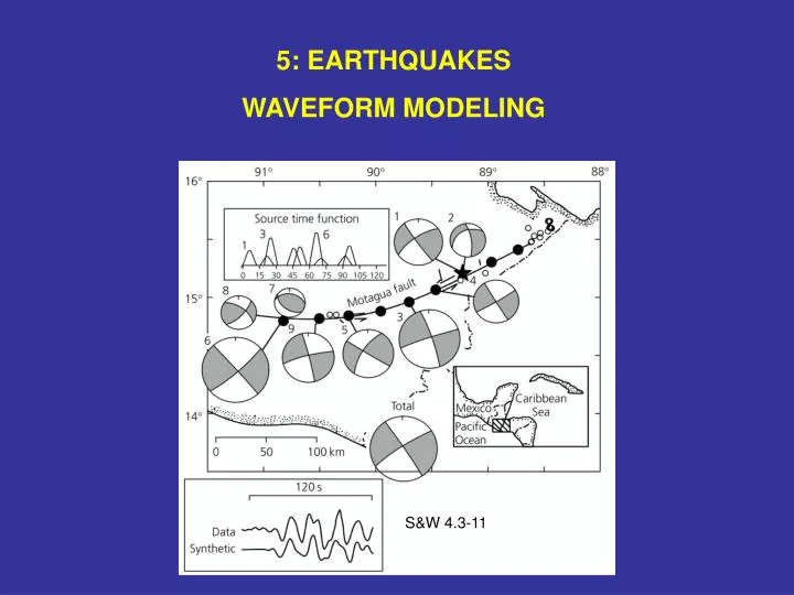
MODEL COMPLEX EVENT BY SUMMING SUBEVENTS 1976 Guatemala Earthquake Ms 7.5 on Motagua fault, transform segment of Caribbean- North American plate boundary Caused enormous damage and 22,000 deaths S&W 4.3-11
ACTUAL EARTHQUAKE FAULT GEOMETRIES CAN BE MUCH MORE COMPLICATED THAN A RECTANGLE Fault may curve, and require 3D-description. Rupture can consist of sub-events on different parts of the fault with different orientations. Can be treated as superposition of simple events. 1992 Landers, California Mw 7.3 SCEC Website
Generally seismograms are dominated by large longer-period waves that arrive after the P and S waves. These are surface waves whose energy is concentrated near the earth's surface. As a result of geometric spreading, their energy spreads two-dimensionally and decays with distance r from the source approximately as r -1 , whereas the energy of body waves spreads three-dimensionally and decays approximately as r -2. Thus at large distances from the source, surface waves are prominent on seismograms.
Love waves result from SH waves trapped near the surface. Rayleigh waves are a combination of P and SV motions.
From geometric spreading alone, expect minimum at =90º, and maxima at 0º and 180º Also have effects of anelasticity
SYNTHESIZE SURFACE WAVES IN FREQUENCY DOMAIN EARTH STRUCTURE SOURCE GEOMETRY
SURFACE WAVE AMPLITUDE RADIATION PATTERNS Amplitude radiation patterns for Love and Rayleigh waves corresponding to several focal mechanisms, all with a fault plane striking North. Show amplitude of surface waves in different directions at same distance Can be generated for any fault geometry and compared to observations - after data equalized to same distance - to find the best fitting source geometry Stein & Wysession, 2003
SURFACE WAVE MECHANISM CONSTRAINTNormal faulting earthquake in diffuse plate boundary zone of Indian Ocean First motions constrain only E-W striking, north-dipping, nodal plane Second plane derived by matching theoretical surface wave amplitude radiation patterns (smooth line) to equalized data. S & W 4.3-13
SURFACE WAVE CONSTRAINT ON DEPTH How well waves of different periods are excited depends on depth S & W 4.3-14 For fundamental mode Rayleigh waves, excitation at given period decreases with source depth h For a given depth, longer periods better excited
Reciprocity principle states that under appropriate conditions the same displacement occurs if the positions of the source and receiver are interchanged Thus if surface wave displacement decreases with depth, deeper earthquakes don’t excite them as well Longer period waves “see” deeper, so better excited for source at given depth
SURFACE WAVE CONSTRAINT ON DEPTH How well waves of different periods are generated depends on depth DEPTH (km) S & W 4.3-14
SURFACE WAVE DIRECTIVITY CONSTRAINT 1964 Mw 9.1 Alaska earthquake 7m slip include finite fault area (500 km long) directivity to match surface wave radiation pattern Pacific subducts beneath North America Kanamori, 1970