Download
1 / 30
330 likes | 539 Vues
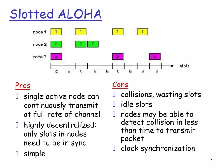
Pros single active node can continuously transmit at full rate of channel highly decentralized: only slots in nodes need to be in sync simple. Cons collisions, wasting slots idle slots nodes may be able to detect collision in less than time to transmit packet clock synchronization.

E N D
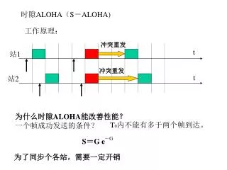
Pros single active node can continuously transmit at full rate of channel highly decentralized: only slots in nodes need to be in sync simple Cons collisions, wasting slots idle slots nodes may be able to detect collision in less than time to transmit packet clock synchronization Slotted ALOHA
suppose: N nodes with many frames to send, each transmits in slot with probability p prob that given node has success in a slot = p(1-p)N-1 prob that any node has a success = Np(1-p)N-1 max efficiency: find p* that maximizes Np(1-p)N-1 for many nodes, take limit of Np*(1-p*)N-1 as N goes to infinity, gives: Max efficiency = 1/e = .37 Slotted Aloha efficiency Efficiency : long-run fraction of successful slots (many nodes, all with many frames to send) At best: channel used for useful transmissions 37% of time! !
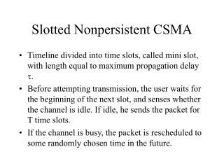
Pure (unslotted) ALOHA • unslotted Aloha: simpler, no synchronization • when frame first arrives • transmit immediately • collision probability increases: • frame sent at t0 collides with other frames sent in [t0-1,t0+1]
Pure Aloha efficiency P(success by given node) = P(node transmits) . P(no other node transmits in [p0-1,p0] . P(no other node transmits in [p0,p0+1] = p . (1-p)N-1 . (1-p)N-1 = p . (1-p)2(N-1) … choosing optimum p and then letting n -> infty ... = 1/(2e) = .18 even worse than slotted Aloha!
CSMA (Carrier Sense Multiple Access) CSMA: listen before transmit: If channel sensed idle: transmit entire frame • If channel sensed busy, defer transmission • human analogy: don’t interrupt others!
CSMA collisions spatial layout of nodes collisions can still occur: propagation delay means two nodes may not hear each other’s transmission collision: entire packet transmission time wasted note: role of distance & propagation delay in determining collision probability
CSMA/CD (Collision Detection) CSMA/CD: carrier sensing, deferral as in CSMA • collisions detected within short time • colliding transmissions aborted, reducing channel wastage • collision detection: • easy in wired LANs: measure signal strengths, compare transmitted, received signals • difficult in wireless LANs: received signal strength overwhelmed by local transmission strength • human analogy: the polite conversationalist
“Taking Turns” MAC protocols channel partitioning MAC protocols: • share channel efficiently and fairly at high load • inefficient at low load: delay in channel access, 1/N bandwidth allocated even if only 1 active node! random access MAC protocols • efficient at low load: single node can fully utilize channel • high load: collision overhead “taking turns” protocols look for best of both worlds!
data data poll “Taking Turns” MAC protocols Polling: • master node “invites” slave nodes to transmit in turn • typically used with “dumb” slave devices • concerns: • polling overhead • latency • single point of failure (master) master slaves
“Taking Turns” MAC protocols Token passing: • control token passed from one node to next sequentially. • token message • concerns: • token overhead • latency • single point of failure (token) T (nothing to send) T data
Summary of MAC protocols • channel partitioning, by time, frequency or code • Time Division, Frequency Division • random access (dynamic), • ALOHA, S-ALOHA, CSMA, CSMA/CD • carrier sensing: easy in some technologies (wire), hard in others (wireless) • CSMA/CD used in Ethernet • CSMA/CA used in 802.11 • taking turns • polling from central site, token passing • Bluetooth, FDDI, IBM Token Ring
LAN technologies Data link layer so far: • services, error detection/correction, multiple access Next: LAN technologies • addressing • Ethernet • hubs, switches
5.4 Link-Layer Addressing 5.5 Ethernet 5.6 Hubs and switches Link Layer
MAC Addresses and ARP • 32-bit IP address: • network-layer address • used to get datagram to destination IP subnet • MAC (or LAN or physical or Ethernet) address: • function:get frame from one interface to another physically-connected interface (same network) • 48 bit MAC address (for most LANs) • burned in NIC ROM, also sometimes software settable
LAN Addresses and ARP Each adapter on LAN has unique LAN address Broadcast address = FF-FF-FF-FF-FF-FF 1A-2F-BB-76-09-AD LAN (wired or wireless) = adapter 71-65-F7-2B-08-53 58-23-D7-FA-20-B0 0C-C4-11-6F-E3-98
LAN Address (more) • MAC address allocation administered by IEEE • manufacturer buys portion of MAC address space (to assure uniqueness) • analogy: (a) MAC address: like Social Security Number (b) IP address: like postal address • MAC flat address ➜ portability • can move LAN card from one LAN to another • IP hierarchical address NOT portable • address depends on IP subnet to which node is attached
Question: how to determine MAC address of B knowing B’s IP address? ARP: Address Resolution Protocol • Each IP node (host, router) on LAN has ARP table • ARP table: IP/MAC address mappings for some LAN nodes < IP address; MAC address; TTL> • TTL (Time To Live): time after which address mapping will be forgotten (typically 20 min) 137.196.7.78 1A-2F-BB-76-09-AD 137.196.7.23 137.196.7.14 LAN 71-65-F7-2B-08-53 58-23-D7-FA-20-B0 0C-C4-11-6F-E3-98 137.196.7.88
A wants to send datagram to B, and B’s MAC address not in A’s ARP table. A broadcasts ARP query packet, containing B's IP address dest MAC address = FF-FF-FF-FF-FF-FF all machines on LAN receive ARP query B receives ARP packet, replies to A with its (B's) MAC address frame sent to A’s MAC address (unicast) A caches (saves) IP-to-MAC address pair in its ARP table until information becomes old (times out) soft state: information that times out (goes away) unless refreshed ARP is “plug-and-play”: nodes create their ARP tables without intervention from net administrator ARP protocol: Same LAN (network)
5.4 Link-Layer Addressing 5.5 Ethernet 5.6 Hubs and switches Link Layer
Ethernet “dominant” wired LAN technology: • cheap $20 for NIC • first widely used LAN technology • simpler, cheaper than token LANs and ATM • kept up with speed race: 10 Mbps – 10 Gbps Metcalfe’s Ethernet sketch
Star topology • bus topology popular through mid 90s • all nodes in same collision domain (can collide with each other) • today: star topology prevails • active switch in center • each “spoke” runs a (separate) Ethernet protocol (nodes do not collide with each other) switch bus: coaxial cable star
Ethernet Frame Structure Sending adapter encapsulates IP datagram (or other network layer protocol packet) in Ethernet frame Preamble: • 7 bytes with pattern 10101010 followed by one byte with pattern 10101011 • used to synchronize receiver, sender clock rates
Ethernet Frame Structure (more) • Addresses: 6 bytes • if adapter receives frame with matching destination address, or with broadcast address (e.g. ARP packet), it passes data in frame to network layer protocol • otherwise, adapter discards frame • Type: indicates higher layer protocol (mostly IP but others possible, e.g., Novell IPX, AppleTalk) • CRC: checked at receiver, if error is detected, frame is dropped
Unreliable, connectionless service • Connectionless: No handshaking between sending and receiving adapter. • Unreliable: receiving adapter doesn’t send acks or nacks to sending adapter • stream of datagrams passed to network layer can have gaps • gaps will be filled if app is using TCP • otherwise, app will see the gaps
No slots adapter doesn’t transmit if it senses that some other adapter is transmitting, that is, carrier sense transmitting adapter aborts when it senses that another adapter is transmitting, that is, collision detection Before attempting a retransmission, adapter waits a random time, that is, random access Ethernet uses CSMA/CD
1. Adaptor receives datagram from net layer & creates frame 2. If adapter senses channel idle, it starts to transmit frame. If it senses channel busy, waits until channel idle and then transmits 3. If adapter transmits entire frame without detecting another transmission, the adapter is done with frame ! 4. If adapter detects another transmission while transmitting, aborts and sends jam signal 5. After aborting, adapter enters exponential backoff: after the mth collision, adapter chooses a K at random from {0,1,2,…,2m-1}. Adapter waits K·512 bit times and returns to Step 2 Ethernet CSMA/CD algorithm
Jam Signal: make sure all other transmitters are aware of collision; 48 bits Bit time: .1 microsec for 10 Mbps Ethernet ;for K=1023, wait time is about 50 msec Exponential Backoff: Goal: adapt retransmission attempts to estimated current load heavy load: random wait will be longer first collision: choose K from {0,1}; delay is K· 512 bit transmission times after second collision: choose K from {0,1,2,3}… after ten collisions, choose K from {0,1,2,3,4,…,1023} Ethernet’s CSMA/CD (more)
CSMA/CD efficiency • Tprop = max prop between 2 nodes in LAN • ttrans = time to transmit max-size frame • Efficiency goes to 1 as tprop goes to 0 • Goes to 1 as ttrans goes to infinity • Much better than ALOHA, but still decentralized, simple, and cheap
application transport network link physical fiber physical layer copper (twister pair) physical layer 802.3 Ethernet Standards: Link & Physical Layers • many different Ethernet standards • common MAC protocol and frame format • different speeds: 2 Mbps, 10 Mbps, 100 Mbps, 1Gbps, 10G bps • different physical layer media: fiber, cable MAC protocol and frame format 100BASE-T2 100BASE-FX 100BASE-TX 100BASE-BX 100BASE-SX 100BASE-T4