Download
1 / 19
190 likes | 268 Vues
Learn about identifying and correcting signals corrupted by overflow in Digital Signal Processing. Explore a new moving average-based method to unwrap and correct overflowed signals. Discover how to handle noisy signals and make corrections effectively.

E N D
A Method to Correct Data Corrupted by Overflow Ben Christensen Jay Brady Dec. 5, 2013
Topics • A brief introduction to overflow. • How do we identify a signal which has been corrupted by overflow? • How can we correct a corrupted signal? • What kind of signals can be corrected? • New moving average based unwrap method. • Conclusion.
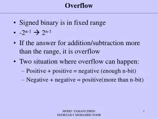
Overflow • Overflow is a problem that can occur in Digital Signal Processing (DSP). • Overflow occurs when a value is represented in binary using an insufficient number of bits. • Systems are usually designed to avoid overflow, but this is not always possible.
Overflow The value of ‘5’ using two’s compliment is 0101 • this requires 4 bits -- 1 ‘sign’ bit plus 3 ‘value’ bits If you try to represent a number using fewer bits, you may lose information and possibly change the sign bit. 0101 has a decimal value of 5 101 has a decimal value of -3!
Overflow • Example: 9-bit Sine wave represented with 8 bits
Overflow Identification • For continuous signals, look for sharp jumps or discontinuities. • If the signal is noisy, you need to look at the distribution. • The distribution will be limited to values within the representable range
Overflow Identification • Example:
Correcting Signals with Overflow • If continuous and noise-free, a simple ‘unwrap’ function can be used. • But how can we correct the signal if noise is present? • A more sophisticated ‘unwrap’ function can be used.
Assumptions • The signal must be slowly-varying. • The signal must be finely sampled. • The noise cannot exceed the total bit-range. • Our simulations were done using fairly low-frequency sinusoids.
Signal Model • Signals are sinusoidal with added Gaussian noise.
Signal Model • If the signal overflows, it has an added ‘overflow factor.’ • m – number of times the signal has overflown (positive or negative). • b – number of bits.
Moving Average Unwrap • If can be subtracted from the original signal can be restored. • The trick is finding mand n (i.e. how much correction and where?)
Correcting the signal • Regions of overflow are identified using a moving average estimator • The difference between the moving average and signal must be under the overflow detection threshold for some number of samples “c” • The value of the function before and after these regions are used to determine the correction factor needed ( -2b, 0, or 2b) • The areas of overflow are removed, and the correction terms added
Conclusions Continuous signals with added noise that suffer from overflow can be corrected for given: • The sampling frequency is much greater than frequencies that make up the signal • The noise is limited below the bin limits