Download
1 / 25
480 likes | 673 Vues
Dial Indicator 를 이용한 Shaft Alignment 의 이해와 절차. Introductions. What exactly is shaft alignment? Rotating axes must be colinear during operation. Introductions. Type of misalignment Parallel Misalignment Vertical & Horizontal offset Angular Misalignment Vertical & Horizontal Angularity

E N D
Introductions • What exactly is shaft alignment? • Rotating axes must be colinear during operation.
Introductions • Type of misalignment • Parallel Misalignment • Vertical & Horizontal offset • Angular Misalignment • Vertical & Horizontal Angularity • Combined Misalignment • Parallel Misalignment + Angular Misalignment
Introductions • What is the objective of accurate alignment? • To increase the operating lifespan of rotating machinery. • Reduce excessive vibration • Reduce bearing, coupling & seal failure.
Introductions • What are the symptoms of misalignment? • Premature bearing, seal, shaft, or coupling failures. • Excessive radial and axial vibration. • High casing temperatures at or near the bearings. • Excessive amount of oil leakage at the bearing seals. • Loose foundation bolts or broken coupling bolts. • The shafts are breaking (or cracking) at or close to the inboard bearings or coupling hubs.
Laser Introductions • Alignment Methods & Resolution
Introductions • Alignment Tolerance
Alignment Procedure • What does take to do each step in the alignment procedure? • Preparation - tools, people, training. • Obtain information on the machine being aligned. • Preliminary checks : • Runout, soft foot, coupling, bearings, foundation, base plate, and piping strain on the machines. • Measure the shaft positions. • Decide who needs to be moved (which way and how much) and then physically reposition the machine(s) vertically, laterally and axially. • Install coupling and check for rotational freedom of drive train if possible. • Run and check the machinery.
Alignment Procedure • Preliminary checks : • Foundation & Baseplate Pads • Piping Strain • Vertical & Horizontal Limit = 0.05 mm • Runout • Shim-pack • Soft Foot • Limit = 0.05 mm
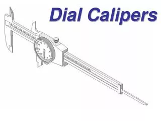
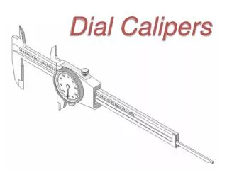
Alignment Procedure • Soft Foot checks • Dial Gage • Feeler Gage
Outer Race Inner Race Alignment Procedure • Runout • Shaft & Coupling • Rolling Element Bearing
0 0 90 10 80 20 4 1 30 70 60 40 2 3 50 Alignment Procedure • Dial Indicator • Plus & Minus Sign
“A” α 0.20 mm α “B” 0 “B” 1/100 mm +20 +20 +40 Alignment Procedure • Indicator Readings • Amount of Offset = TIR/2, TIR: Total Indicator Readings • Top + Bottom = Right + Left
0.05 mm 0.05 mm Alignment Procedure • Bar SAG • SAG = TIR 2 Mandrel Amount of SAG ( - )
Machine “A” of “A” 0.05 mm 0.20 mm TRUE OFFSET of “B” 0.15 mm Machine “B” 0 0 0 SAG Readings Corrected Indicator Readings Measured Readings “B” C C L L +15 20 -5 +15 20 -5 40 +30 -10 Alignment Procedure • Corrected Indicator Readings • True Indicator Readings = Measured Readings – Sag Readings - =
Alignment Procedure • Alignment Methods Using Indicator • Rim & Face Shaft Alignment • Reverse Shaft Alignment • Applications • Rim & Face Shaft Alignment • Trains where one shaft can’t be rotated during the alignment process. • Machines with coupling hubs that are axially close to each other. • Machines that have large diameter couplings. • Small general purpose machines • Reverse Shaft Alignment • Long span machines • Machines that require precision alignment.
Rim & Face Shaft Alignment • Disadvantages • Coupling hub runout will induce an error into the readings. • Radial runout up to 0.05 mm • Face runout up to 0.01 mm • Machines with sleeve bearings can have a face reading error. • It is necessary to locate the rotor in a fixed axial position for each sweep. • On machines with a large axial floats, • such as motor with sleeve bearings.
Fixed Machine Moveable Machine Rim & Face Shaft Alignment • Typical Set-up View from Fixed to Moveable Rim Indicator Face Indicator Diameter at Face Indicator [ A ] Near Foot Far Foot Distance to Near Foot [ B ] Distance to Far Foot [ C ]
0 0 0 0 0 0 -4 0 -4 -2 0 -2 +7 +10 -3 -3 +8 +5 -6 0 -6 -6 +12 +18 Rim & Face Shaft Alignment • Offset Misalignment Vertical Rim Readings Rim Readings Horizontal Measured Readings SAG Readings Corrected Readings Moveable Machine 0.09 mm Fixed Machine Vertical Offset (Side View)
0 0 -4 -2 +10 +8 -6 +18 Rim & Face Shaft Alignment • Angular Misalignment Face : ANGnf = A : B ANGnf = Face x {B/A} A = 8 α Face : ANGff = A : C ANGff = Face x {C/A} Face Corrected Readings Moveable Machine ANGnf = -30 ANGnf = -6 x {21/8} = -15.75 α α Fixed Machine B = 21 C = 40 Vertical Angular Misalignment (Side View)
Fixed Machine Moveable Machine Reverse Shaft Alignment • Typical Set-up View from Fixed to Moveable Distance of face to face [ D ] Near Foot Far Foot Distance to Near Foot [ B ] Distance to Far Foot [ C ]
+ - 0 0 -5 Fixed Machine Fixed Machine - + +10 12.5 20 +5 +14 -15 +6 -10 +20 Reverse Shaft Alignment • Graphic Expression (Vertical Movements) Up Down Vo=(T-B)/2 Vertical Misalignment (Side View)
0 0 Fixed Machine Fixed Machine +5 +14 +6 -15 +20 -10 Reverse Shaft Alignment • Graphic Expression (Horizontal Movements) Ho=(R-L)/2 Left 11 32 + - -4 Right -10 - + Horizontal Misalignment (Top View)
Movement • Vertical Movement
Movement • Horizontal Movement