Download
1 / 16
170 likes | 376 Vues
Cisco 6500 E-Series Chassis Up-grade. Presented by Del Harris. Covered Today. Replacement Preparation Replacement Post Replacement Clean-up. Replacement Preparation. Document Limitations. Procedure assumes: New chassis has been ordered and has been received from Cisco.

E N D
Cisco 6500 E-Series Chassis Up-grade Presented by Del Harris
Covered Today • Replacement Preparation • Replacement • Post Replacement Clean-up
Document Limitations Procedure assumes: New chassis has been ordered and has been received from Cisco.
Typical Replacement Team & Execution • Chassis replacement requires at least two people minimum, with three people as optimum. • One person to coordinate the switch chassis hardware setup, IOS configuration, chassis installation activation monitoring and if needed activation changes. • Two people to coordinate switch label preparation and chassis installation. • Chassis replacement outage with new supplies and additional new cards, typically so far has taken two hours to complete. • Schedule outage for 2.5 to 3.0 hours and send outage change control. • Outage notification should include link to Switch ports, should NCAB & NNAG individuals a specific map of the outage area.
Preparation to switch receiving new chassis up-grade • Verify cable labeling at switch: Should have good readability and accuracy • Sup. cards • Fiber (Trunks) • UTP (Console) • Fiber cards • User\Machine direct • Verify accuracy of label • Intermediate Patch (Cisco to distribution panel) • Card\slot and group sequence label • Individual port sequence labels • UTP cards • User\Machine direct • Verify accuracy of label • Intermediate Patch (Cisco to distribution panel) • Card\slot and Group sequence label • Individual port sequence labels • Power Supplies • Power Cords • UPS or building (Shows supply positions)
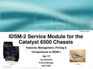
New Switch Chassis Preparation • Unpack (But leave on delivered pallet) • Mount rack ears if not already. • Do not install supplied cable management under rack ears, unless installing chassis where no rack cable management is provided. • Install Fan Blade • Label Chassis • Switch ID • Slot ID’s • Install any new cards at final locations in chassis if part of up-grade. • Do not install new power supplies yet, if part of up-grade. • Deliver Chassis and supplies to switch up-grade location.
Prior to outage • Save switch configuration to flash • Optional: Print a copy of switch port configuration, from the NETS port lists. • Have during chassis replacement.
Chassis Replacement • Call NOC before starting work. • Shut off power supplies. • Start removing cables from the top of the switch and working toward the bottom. • Be careful to keep fiber ends clean. • Remove the chassis rack screws. • Do Not remove the lower screws in the chassis tray. • Remove the chassis ground cable. • Remove the switch power supplies. • Secure all cables back so cards and switch can be removed from tray.
Chassis Replacement • With non E chassis switch still in rack in it’s tray, set up static system and transfer cards to new E-chassis in same slot positions. • Install new E-chassis with cards in rack tray. • Secure new E-chassis with rack screws. • Install power supplies and chassis ground cable • Start installing cables from the bottom of the switch and working toward the top.
Chassis Replacement & Power-up • Have second person verify re-cabling. • Setup boot monitor via the console or Network and power-up. • If needed upon boot completion, update switch configuration for any new card changes during up-grade. • Monitor to see if POE devices, VOIP and AP’s, come up. • Call the NOC to verify, Nagios for active alarms related to closet. • Reply to Outage Notice that work is complete.
Post Replacement • Verify all up-graded switch cabling is re-managed and management covers are in place. • Clean up floor of any debris and remove any unnecessary tools or documents. • Place the old chassis and power supplies on the empty E-chassis shipping pallet and transport non E-chassis and hardware back to ML-34, for trade in.
Procedure Document Cisco Chassis Replacement Procedure http://www.cisl.ucar.edu/nets/devices/eswitches/chassis-replace.html