Download
1 / 8

E N D
Frame Relay Frame Relay is a fast packet-switching technology introduced in 1992. fast packet-switching means, high-speedcommunications and low-delay networking. Fast packet is a "hold and forward" technology designed to reduce delay, reduce overhead and processing, improve speed, and reduce costs. It isdesigned to run on high-speed circuits with low (or no) error rates. Errors are corrected at the two ends, instead of every step along the route
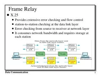
Frame Relay versus X.25 Frame Relay, as stated, is a fast packet-switching technology used for the packaging andtransmission of data communications. Moreover, Frame Relay packages the data into a data linklayer frame used to carry the data across the network on apermanent virtualcircuit(PVC) without all the handling of the X.25 networks. Although X.25 acknowledges everypacket traversing the network, Frame Relay does not useacknowledgments(ACKs) ornegativeacknowledgments(NAKs). Also, when an X.25 packet is corrupted, the network node requests aretransmission, which is not so on Frame Relay. Both of the services do, however, use a statisticalTDM concept. Table 11-1 is a summary of the comparison of X.25 and Frame Relay services.
Frame Relay’s Frame The beginning of the frame starts with an opening flag, the opening flag depicts that the frame is started. Next, a two-byte sequence defines the addressing of the frame. This is called the Data Link Connection Identifier (DLCI). By very nature of the title (DLCI), we can assume that Frame Relay works at the data link layer. Following the data field in the Frame Relay frame is a cyclic redundancy check (CRC) used only to check for corruption. The CRC determines if the frame or the address information is corrupt. If so, the frame is discarded; if not, the frame is forwarded. There is no ACK or NAK in the Frame Relay transmission along the route. Lastly, there is a closing flag on the frame, indicating that the transmission of the frame is ended
Frame Figure
Asynchronous Transfer Mode (ATM) Overview In 1992, a group of interested parties developed a set of standards-based specifications called the Asynchronous Transfer Mode (ATM). This was a step at developing a single set of standards for the integration of voice, data, video, and multimedia traffic on a single backbone network. Prior to this development, the industries offered separate standards and networks for voice, others for data, and still others for video communications.
ATM What Is ATM? ATM is a member of the fast packet-switching family called cell relay As part of its heritage, it is an evolution from many other sets of protocols. In fact, ATM is a statistical time-division multiplexed (TDMed) form of traffic that is designed to carry any form of traffic and enables the traffic to be delivered asynchronously to the network. When traffic in the form of cells arrives, these cells are mapped onto the network and are transported to their next destination. When traffic is not available, the network will carry empty (idle) cells because the network is synchronous. ATM is one technology for voice, data, video and multimedia. It provides bandwidth on demand as needed
Mapping Circuits Through an ATMNetwork Mapping Circuits Through an ATM Network. The connection is built into a routing table in each of the switches involved with the connection from end to end. As such, the switches only need to look up a table for the incoming port and channel and then determine the mapping (in the same table) for the output port and channel. Using virtual path identifiers (VPI) and virtualchannel identifiers(VCI),