Download
1 / 25
250 likes | 358 Vues
LMS2000 SYSTEM. World’s 1st truly integrated wireless Internet system Provides Wireless Internet access 11 Mbps raw data rates using DSSS in the 2.4 GHz ISM band Fixed Wireless Access data system Target multiple small to large size offices Services include: email WEB browsing FTP.

E N D
World’s 1st truly integrated wireless Internet system Provides Wireless Internet access 11 Mbps raw data rates using DSSS in the 2.4 GHz ISM band Fixed Wireless Access data system Target multiple small to large size offices Services include: email WEB browsing FTP Introduction
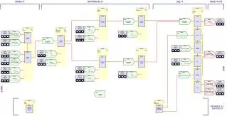
End User Modem (EUM) Communications Access Point (CAP) Network Access Point (NAP) system management and access to the Internet and system wide services Backhaul Infrastructure components antennae, cable, mounts LMS2000 Main Blocks
Data network infrastructure NMS Enhanced system maintenance Enhanced subscriber management RADIUS compatible OAM support (SNMP managed) Alarming The NAP
Supports 7 CAPS Half height indoor free-standing 19” equipment cabinet Equipment includes: High speed CISCO router 100BaseT CISCO Ethernet switch UPS NMS Workstation More NAP
Directional gateway between the LMS2000 network and the Internet SNMP Managed GUI configured CISCO Router
Gateway that moves data between the NAP and the CAP Enables connecting up to seven CAPs to one NAP Ethernet switch via 10/100 BaseT compatible Backhaul. Serves as the system connection point for the NMS workstation. SNMP managed GUI configured CISCO Ethernet Switch
EUMs transmit data at the max rate which creates competition for bandwidth Prevents inconsistent data transmission and overloading the system Provides for the allocation of data traffic rates to and from the EUM Provided by the router for smaller systems, dedicated Bandwidth Network Manager (BWM) in large systems NMS application allocates service levels to each EUM Allows differentiated service levels generating additional revenue SNMP managed GUI configured Bandwidth Management
An alarm will indicate power shutdown which allows operator a minimum of 10 minutes to perform a graceful shutdown. Continuous protection from power surges, spikes, or sags on the main power lines. SNMP managed GUI configured NAP UPS
Personal computer equipped with a printer, keyboard, mouse, backup tape drive, and a uninterruptible power supply (UPS) with APS PowerChute PLUS software for monitoring system power levels. The NMS Workstation contains the software for managing the LMS2000 system. NMS Workstation
Microsoft Windows NT 4.0 Workstation (with Service Pack 6a) WaveRider LMS Network Management System Microsoft SQL Server Vircom VOP RADIUS server controls the logon and authentication access for the EUMs. Each EUM has a coded ID/password combination that RADIUS will use to recognize the modem. Castlerock SNMPc Server Tardis Timeserver provides time synchronization between the Internet and the CAP and NAP hardware APS PowerChute PLUS Veritas Backup Exec with Microsoft SQL Agent Mirrored Hard Drive Disc System RAID 2 NMS Software
Provides the path for the NMS to the EUMs Provides the central radio access point for EUMs Provides a path for Internet data to travel between the EUM and the NAP for routing to the Internet. Up to 3 active channel units - hot swappable Extra channel unit and switch matrix for redundancy UPS 10/100 BaseT connection for backhaul The CAP
3 CAP channel units (CCU) Cisco Ethernet switch Uninterruptible power supply (UPS) Additional channel unit and RF switch matrix for channel unit redundancy (option) Additional hardware supporting the CAP RF subsystem, including antennae, antennae mount, lightning arrestors, cabling, and connectors Backhaul equipment not contained in the CAP cabinet More CAP
Based on proprietary WaveRider wireless and IP technology Wired-to-wireless conversion 11 Mbps wireless data rate IP router function Up to 30 EUM’s FCC/IC approved SNMP managed GUI configured CCU
Gateway that moves data between the CCUs and the backhaul interface Collects data from multiple CCUs and directs all the data into a single stream (aggregates) then sends the streamed data to the external backhaul In the NAP-CAP direction the Ethernet switch collects data from the backhaul and fans it out to multiple CCUs GUI configured CAP CISCO Ethernet Switch
An alarm will indicate power shutdown which allows operator a minimum of 10 minutes to perform a graceful shutdown. Continuous protection from power surges, spikes, or sags on the main power lines. SNMP managed GUI configured CAP UPS
Determined by the configured size of the CAP, the available backhaul infrastructure and spectrum in the service area, and the distance between the CAP and the NAP Consult WaveRider System Engineer for determining Should be SNMP managed Fast as the slowest link Backhaul
Based on WaveRider proprietary wireless and IP technology IP router function FCC/IC approved SNMP managed GUI configured EUM
System reliability is measured by the availability of the system to the subscribers. Down time is a critical factor in maintaining customer satisfaction and a solid revenue flow. Need
Industry leading Cisco routers & switches to ensure long term reliability and industry compatibility Key system elements (NAP, NMS, CAP) protected from power outages by dedicated UPS units Radio modules based on field proven 802.11 ISM band integrated components and WaveRider modem technology Design Features
Policy-based bandwidth management ensures disciplined control of all access to the valuable system bandwidth resources Back-up CAP channel unit, CCU, constantly monitors active channel units and automatically replaces a defective channel Design Features
GUI based network configuration with rule checking Automatic database synchronization RAID 2 data storage protects against disc failure Database backup utility RFSM GPIO for External Alarms Centralized NetworkManagement System
Automated system monitoring and messaging to provide warnings re: approaching overload conditions, performance degradation or failures Automatic monitoring of hardware configuration and software version Remote downloading of new/upgraded software throughout the network Centralized NetworkManagement System