Download
1 / 49

E N D
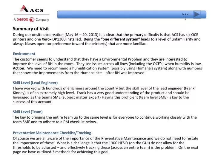
Next Summary of Visit During our onsite observation (May 16 – 20, 2013) it is clear that the primary difficulty is that ACS has six OCE printers and one Xerox DP1300 installed. Being the “one different system” leads to a level of unfamiliarity and always biases operator preference toward the printer(s) that are more familiar. Environment The customer seems to understand that they have a Environmental Problem and they are interested to improve the level of RH in the room. They see issues across all lines (including the OCE’s) when humidity is low. Action: We need to recommend a humidification system (possibly using Humana’s system) along with numbers that shows the improvements from the Humana site – after RH was improved. Skill Level (Lead Engineer) I have worked with hundreds of engineers around the country but the skill level of the lead engineer (Frank Kinney) is of an extremely high level. Frank has a very good understanding of the product and should be leveraged as the teams SME (subject matter expert)Having this proficient (team level SME) is key to the success of this account. Skill Level (Team) The key to bringing the entire team up to the same level is for everyone to continue working closely with the team SME and to adhere to a PM checklist below. Preventative Maintenance Checklist/Tracking Of course we are all aware of the importance of the Preventative Maintenance and we do not need to restate the importance of these. What is a challenge is that the 1300 HFSI’s (on the GUI) do not allow for the thresholds to be adjusted – and effectively tracking these (across an entire team) is the problem. On the next page we have outlined 3 methods for achieving this goal.
Prev. Click Choices Below Preventative Maintenance/Tracking Methods As mentioned in the previous slide – tracking PM’s and “Adjusting Thresholds” is the key to effective maintenance and keeping the entire team on the same page. Outlined below are (3 methods) of Tracking PM’s Manual/ Log Sheet We have developed a manual PM checklist (next slides) that will provide your team with the updated frequency to be performing certain checks. Unfortunately manual processes lack the ability to adjust threshold levels. Proceed to PM Checklist. HFSI – PC Tool (HFSI.exe) Several years ago I developed a touchscreen HFSI.exe program that can run on a PC and will give you the ability to change thresholds and ADD custom items that you wish to track. The downside is that this has to reside on a single PC but this does not make it accessible to the entire team. It can be added to the GUI – but then a keyboard would have to be connected anytime Threshold Changes need to be adjusted. I have attached this tool to this presentation if the team would like to use it. HFSI – Cloud Based A cloud-based HFSI system is about 50% completed – but further work would needed to make it available to the field. This is an option - but costs would be involved to my manager for any further investment of time. This tool (if completed) would allow the team to ADD, ADJUST, TRACK any HFSI and the data would be available in “real-time” and the data could be viewed by logging into the secure cloud server. This option also allows for “Being There” Video Support through the WebEx app.
Prev. • Custom Thresholds (updated on the cloud) • Team members always in-sync with component status. • Ability to ADD, TRACK any Custom HFSI. • Second Level can adjust thresholds on the fly. • Data available in “real-time” for instant site snapshot • from secure server.
Prev. I wrote this program 10 years ago but it is not cloud-based. It allows you to add/track CUSTOM HFSI and gives you warning when you are approaching the set threshold. The thresholds and/or HFSI items can be changed on the fly. The problem with this is that it has to reside on ONE PC or on the printer GUI. (Thresholds require keyboard to change but the reset and meter reads are touchscreen compatible)
We are able to instantly see the component replacement in “real time” and are notified immediately when systems exceed thresholds. Thresholds are updated on the cloud which will instantly change or extend the expected HFSI value.
Prev. Interactive PM Document DP650/1300 Version 1.2 START • This document was written to help the CSE to perform preventative maintenance and will provide visual guidance. Please note that the CSE should use Service Manual, Section 1, (SCP3, Service Call Procedures #3) for further details. Also we update EDOC frequently with Bus Notes.
PM Main Menu Home Page Cleaning Index Sensor Check TOF DRS Click the blue pins to navigate to the areas we have added content.
Index Main Menu Xerox Internal Use Only – Xerox Confidential – Xerox Third Party Confidential – Xerox Personal Confidential
Main Menu Click any item to the left to navigate to correct cleaning page. To view full cleaning intervals click the button below. CLEANING INTERVALS Xerox Internal Use Only – Xerox Confidential – Xerox Third Party Confidential – Xerox Personal Confidential
General Cleaning Main Menu
Observations • Keeping this machines clean is key to their overall performance. Any machine that has an increased level of toner contamination can be a sign of a system running with excessive toner density.Toner density can be directly proportionate to incorrect DRS - Drum Radial Spacing and this should be examined and reset back to specification.
Suggestion - Sub Assemblies Action Need to have one complete lamp assembly in office. Assembly takes between 1 – 1.5 hours to clean/rebuild flash unit. Through logs – it appears that the lamp unit needs to be rebuilt at 20M (average) This is up from original number of 12M. Part Number: 500K90730 • Flash Lamp Assembly Xerox Internal Use Only – Xerox Confidential – Xerox Third Party Confidential – Xerox Personal Confidential
Suggestion - Cleaning • Fuser Manifold Assembly
Suggestion - Cleaning • Action • Smoke Filter Cavity • Restricted air flow- Could toggle Smoke Filter End Life Switch • FUJI recommends the housing be cleaned at 1.5M. • Need to develop a technique for cleaning this cavity . • Associated Fault: Higher frequency of Smoke Filter failures. • Smoke Filter Housing Gasket drooping down into air passage way.
Inspection - Sub Assemblies • Action • Smoke Filter Cavity • Restricted air flow- Could toggle Smoke Filter End Life Switch • FUJI recommends the hose be cleaned at 1.5M. Fairly difficult to do – but we may wantto implement an inspection. • Need to develop a technique for inspecting the hoses and pressure switches. • Associated Fault: Higher frequency of Smoke Filter failures. • Smoke Filter Assembly Xerox Internal Use Only – Xerox Confidential – Xerox Third Party Confidential – Xerox Personal Confidential
Inspection - Sub Assemblies • Transfer Guide Tape
Inspection – Roller Covering Action Urge Unit Rollers The urge unit rollers also have a tape covering that wears over time. This loss of covering can cause a host of errors within the systems. The tape appears to be showing wearing on many systems. Currently we do have one set in stock 063E99010 • Urge Unit Rollers – Tape Covering
Inspection - Sub Assemblies • Brake Roller Tape
Suggestion - Sub Assemblies • Transfer Unit Center Finger Guide
Suggestion – Parts • B Size Tool
DRS – Radial Set-up Index Main Menu • We recommend that accounts that have a high level of quality expectations and/or volume – invest in the digital drum radial tool vs. using the dummy drum. • This tool was initially specified for the 490/980 color product as it was essential that our drum radials were very accurate – and within tight tolerances. • With the 650/1300 – we are now finding that using this tool will ultimately save money over the long run. As saving as little as (2) drums will pay for the updated tool. • As shown to the right – the tool comes with its own calibration jig that allows you to “zero out” the tool so when it is placed inside the machine you will be able to perform a precise adjustment each and every time.
Corotron Cleaning Unit(s) Index Main Menu • The Corotron cleaners on this system will need to be inspected and cleaned every 2 weeks of operation. It is important as the worm gears will bind within the cleaner head leading to “Cleaner Failure Errors” • Wipe/clean the worm gear with a cloth soaked with film remover and let it dry. Next apply a coating of dry lube to the surface of the worm gear so that it will easily travel within the cleaner unit. The photo above shows a worm gear and cleaner head with a substantial amount of rust and contamination. This unit had constant failures – but by applying dry lube (molykote) 70P00072 we were able to restore this unit back to smooth operation.
Developer Drive Inspection Index Main Menu • We are recommending that all drives (not just developer drives) are fully inspected and repaired as needed every 6million feet of operation. • A general observation while doing some light vacuuming will alert you to belts and pulleys that are starting to show wear. This simple inspection will allow you to order suspect parts weeks before they will actually fail and will eliminate surprise failures. • The photo to the right shows a drum drive idler that was discovered during a cleaning cycle and was ready to fail within the next few hours of operation – which would have led to hours of downtime for the customer. • At this same time perform Developer Cleaning Routine. Blocked Exit Sensor
Brush Housing and Ducts Index Main Menu • Every 9 Million feet we are recommending that the Brush Housing and related ducts are cleaned and inspected. Over time you can see a build-up that will interfere with proper cleaning and suction. Pay close attention to brush drive belt and idler assemblies. When tightening the drive belt – please ensure the belt is not over-tightened which will lead to early failure o f the idler and belt. The belt should have at least ¼” of deflection. (but not too loose to enabling the belt to jump teeth) Blocked Exit Sensor
Cleaning Discharge LED Index Main Menu • At the 6 Million foot interval we are recommending a complete inspection and cleaning of the Discharge LED unit. Keeping this clean will reduce contamination and possible background. • The cleaning brush is not able to fully clean the surface of the drum when this unit is dirty and we see an increase of overall contamination in many systems. A soft cloth is used so you do not scratch the surface of the LED plastic lens. Make an observation and check consumable counter regarding the life and condition of the LED discharge – and replace as needed. At this same interval please inspect and clean the LED print head. Blocked Exit Sensor
Cleaning LED Print Head Index Main Menu • At the 6 Million foot interval we are recommending a complete inspection and cleaning of the LED print head unit. Over time you will see a build-up which will result in overall light prints, uneven density or light banding on the output due to this contamination. A soft cloth is used so you do not scratch the surface of the LED plastic lens. Make an observation and check consumable counter regarding the life and condition of the LED discharge – and replace as needed. If you have not already done so please clean the Discharge LED at this time as well. Blocked Exit Sensor
Cleaning Tractor Assemblies Index Main Menu • At the 6 Million foot interval we are inspecting and cleaning all 3 tractor assemblies. This is best accomplished by using canned compressed air to blow out each tractor assembly and remove excess paper or toner contamination. At this time inspect tractor belts and drive belts. Also please check the sub-tractor brass pulley for any possible wear. See photo below. Blocked Exit Sensor
Cleaning Paper Transport Index Main Menu • Every 3 Million feet it is essential that we perform a general cleaning of the entire paper path/transport area. The level of paper dust builds up quickly and will eventually migrate into the developer housing and will coat LED bars, corotrons etc. which will lead to PQ defects and unplanned service calls. • This simple routine will have the overall largest payback in reduced service calls. Blocked Exit Sensor
TOF – Starting Point Main Menu This adjustment is one that will not need to be made unless you have been servicing the tractor drives and now have a slight misalignment. If this alignment is required – you will need to loosen the tractor main drive motor belt and advance it by a single tooth on the drive belt so that this correct alignment can be achieved.Click Next Page to see Adj. • If you are printing on perforated paper with a pre-defined top of form – it is important the TOF aligns correctly on alignment ruler of the upstream printer. To check for proper alignment we run the 12” box paper – to verify that perforation lines up to the #12. On some systems you may find that it the perforation ends up on one side or the other and can never line up perfectly to the 12” mark. . If perforation cannot be aligned to the #12 mark during set-up
Clean Developer Housing Index Main Menu • We are recommending a general cleaning/inspection of the entire developer housing every 6M feet. This cleaning will involve the housing being pulled from the machine and placed onto a maintenance table/cart.This cleaning should be performed at the same interval as the Developer Drive Inspection. Rotate the mag rolls backwards to clear the rolls of developer. This will allow you to make a general cleaning and light vacuum around the housing. At this time inspect the drum seals on each end of the housing. Poor seals will lead to toner contamination throughout the printer.
Clean Fuser Assembly Index Main Menu • We are recommending a general cleaning/inspection of the Fuser Assembly every 3 Million feet and the inspection/cleaning of the fuse glass during every unscheduled service call. • This involves cleaning the fuser glass, reflector and cleaning out the fuser manifold. At this time also inspect lamps for possible end-of-life. (Black ends, poor fusing (after cleaning), and have greatly exceeded end of life expectations. Flash Lamp Assembly – BEFORE cleaning Flash Lamp Assembly – AFTER cleaning
Clean Fuser Ducts/Cooling Index Main Menu • One area that is often overlooked is the Fuser Ducts just directly below the flash lamps. These ducts provide essential cooling to the flash lamps and this area needs to be cleaned every 9 Million feet. These photos represent a system that is completely blocked and have no airflow. This often causes premature lamp failure.
Clean Smoke Filter Box Index Main Menu • The smoke filter box can see plenty of contamination if the filter is not fully sealed within the door. As seen in this picture the filter gasket is not functioning and in some cases not existent. • This results in a heavy contamination and an odor into the print room itself.We recommend this to be inspected and cleaned every 9 Million feet of operation. Gasket drooping down into air passage way. This gasket needs to be repaired or replaced.
Clean Smoke Hoses/ Ducts Index Main Menu • At 9 Million feet we are also recommending a full inspection of all smoke filter hoses and fittings. This involves removing these hoses and inspecting them for internal contamination. • By squeezing /flexing these hoses you are able to break loose internal build-up. Not cleaning these hoses on a regular basis will result in a faster build-up and eventual blockage of the entire hose. • At this time also remove, inspect and clean all pressure sensor hoses.
Clean Scuff/Pinch Rollers Index Main Menu • At 6 Million feet we are also recommending a full inspection and cleaning of all scuff and pinch rollers. • Over time these can become misaligned, broken or end up with a toner/paper build up which hinders their performance. • A quick inspection and cleaning will keep these working well. This is a very quick inspection/cleaning and will keep your paper tracking correctly through the printer.
Clean Stacker Swing Guide & Sensors Index Main Menu • Every 15 Million feet we are also recommending a full inspection and cleaning of the stacker swing guide and stacker sensors. To make this convenient we are showing the stacker sensor locations in the illustration to the right.
Check Stacker Drive Belts Index Main Menu • At 15 Million feet it is advisable to check all belts and their appropriate belt tensions within the stacker assembly. • A quick visual check for cracked or loose belts at this time will eliminate many unnecessary emergency calls in the future. • All belts need to be set to their correct deflection so they are not putting excess stress on the idler pulleys. All of theses values are outlined in the service guide in section 11 of adjustments. • It is also recommended that a complete vacuum of this area is performed. Also some compressed air may be needed to dislodge build-up in certain areas.
Clean Power Supply Filters Index Main Menu • At 9 Million we are recommending a full cleaning of all power supply filters. These plugged filters are the leading cause for power supply failures as these supplies pull air from the floor and get contaminated. • In the case of the filters shown to the right they are FULLY blocked and allowed no air flow to these power supplies. Before After
Clean Paper Path Sensor Index Main Menu • Every 3 Million feet we need to locate and clean every paper path sensor. For your convenience we have provided a graphic to help locate these sensors. • There are a couple of ways you can check for proper operation of these sensors. • The first (easier option) is to check the state of the sensor using this procedure below. • Check Sensor State NOTE: A secondary option is to refer to Eureka Tip 915383 to view which sensors are being triggered on the I/O board – by looking at which LED’s are lit.
Check STAMPA/GUI Computers Index Main Menu • At 15 Million feet we are removing both STAMPA and GUI computers from their respective bays. Adhering to anti-static guidelines – clean with canned air all dust and debris from inside each PC. • Once the PC’s are powered up – check for proper fan functionality and check that both DVD drives are functioning.
Toner Blower Assembly Index Main Menu At 9 Million feet we are performing a full inspection and cleaning of the entire Toner Blower Assembly, inspecting hoses and checking all switches for bent or loose actuators. Look for worn seals and/or cracked hoses that will ultimately lead to machine contamination. Clean the waste toner blower, container and filter housing. Check all seals and filters
TOF – Starting Point This adjustment is one that will not need to be made unless you have been servicing the tractor drives and now have a slight misalignment. If this alignment is required – you will need to loosen the tractor main drive motor belt and advance it by a single tooth on the drive belt so that this correct alignment can be achieved.Click Next Page to see Adj. • If you are printing on perforated paper with a pre-defined top of form – it is important the TOF aligns correctly on alignment ruler of the upstream printer. To check for proper alignment we run the 12” box paper – to verify that perforation lines up to the #12. On some systems you may find that it the perforation ends up on one side or the other and can never line up perfectly to the 12” mark. . If perforation cannot be aligned to the #12 mark during set-up
Sensor Integrity Check (Step 1) STEP 1 Main Menu STEP 2 STEP 3 • In a dusty/dirty environment you will run into sensors that are not performing correctly. Sometimes even after cleaning – you will get errors like “paper already loaded” when in fact there is no paper in the printer. • This is quickly resolved by entering into Maintenance Mode and performing a READ of the NVM location OD. Be sure to select I/O under “data reading item” pull-down menu. NOTE: A secondary option is to refer to Eureka Tip 915383 to view which sensors are being triggered on the I/O board – by looking at which LED’s are lit. Click to view sensor locations
Sensor Locations Return
Sensor Integrity Check (Step 2) STEP 1 Main Menu STEP 2 STEP 3 1) In this example you read (33) in location 0D. 2) You convert this HEX number 33 to binary using your calculator on your PWS laptop. 3) This converts to 110011 when you select binary.
Sensor Integrity Check (Step 3) STEP 1 Main Menu STEP 2 STEP 3 4) This binary number is now compared to our chart in GP5 of the service manual. Here you can see how this binary number of 110011 would relate to this chart. 0 0 1 1 0 0 1 1 Reading right to left this scenario shows the “reserved” as ON (but this is not used) – next it shows the EOF sensor detecting paper, the Fuser entry sensor detecting paper and the Fuser middle sensor detecting paper. Using this method is very useful to quickly identify which sensors are detecting paper. When no paper is loaded you should see a value of 01. Which of course when converted to binary will simply be 00000001 – which only shows the reserve bit (not used).
Xerox Internal Use Only – Xerox Confidential – Xerox Third Party Confidential – Xerox Personal Confidential