Download
1 / 54
590 likes | 857 Vues
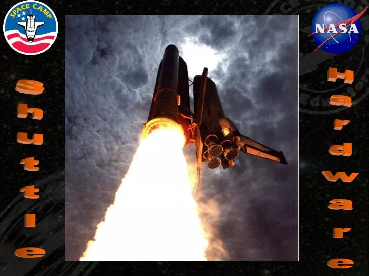
Hardware. Shuttle. Orbiter x1. Space Shuttle Main Engines (SSMEs) x3. Space Transportation System (STS) Four main components Parts are modular Most parts have limited/partial reusability. External Tank (ET) x1. Solid Rocket Boosters (SRBs) x2. Anatomy of an Orbiter.

E N D
Hardware Shuttle
Orbiter • x1 • Space Shuttle • Main Engines • (SSMEs) x3 • Space Transportation System (STS) • Four main components • Parts are modular • Most parts have limited/partial reusability • External Tank • (ET) x1 • Solid Rocket • Boosters (SRBs) x2
Anatomy of an Orbiter Atlantis: OV-104 Endeavour: OV-105 Discovery: OV-103 Lifespan: 100 Missions (Projected) Payload Bay Crew Compartment • Length: 122 ft (37.2 m) • Weight: 153,000 lbs (69,400 kg) no SSME’s • Height: 57 ft (17.3 m) • Width: 78 ft (23.8 m)
The Crew Compartment (Seven people picked to live in a house, a small house) 1 2 • Flight Deck • Mid Deck • Equipment Bay 3
Flight Deck Commander, Pilot, Mission Specialists 1 and 2 sit here during launch and landing • Forward Flight Deck • serves as the cockpit • Aft Flight Deck • contains payload controls
Mid Deck Mission Specialist 3 and any Payload Specialists sit here during launch and landing • Airlock • Modular Lockers • Crew Access Hatch 4 6 2 3 1 2 5 1 • Rigid Sleep System • Waste Management • Modular Galley
Equipment Bay • Equipment, Experiment, and Trash Storage • Stowage For MS3 and PS Chairs • LiOH Canisters • Water Tanks
Payload Bay (Midfuselage) • Dimensions: • Length 60 ft (18.3 m) • Width 15 ft (4.6 m) • Height 13 ft (3.4 m) • Port RMS Mounting • Starboard OBSS mounting • Payload Weight Capacity • 60,000 lbs (27,215 kg) Max To-Orbit • 35,000 lbs (15,876 kg) Max Landing Docking Adapter/Airlock Multi Purpose Logistics Module (MPLM)
Redundant Systems (Back-ups for Back-ups) • General Purpose Computers (GPCs) • 5 Computers IBM AP-101s CPUs • 256k by 32 Bit Memory Module • If one fails Orbiter it can safely function with other four • Perform Guidance, Navigation, and Control
Redundant Systems (Back-ups for Back-ups) • Auxiliary Power Units (APUs) • Three independent systems operate launch and landing control systems • Provide power for the Orbiter hydraulics • One can fail and the orbiter can still safely function
Redundant Systems (Back-ups for Back-ups) • Fuel Cells (FCs) • Electrical power for the orbiter is provided by 3 Fuel Cells • Hydrogen and Oxygen are combined to produce electricity • By-product is water • Environmental Control and Life Support Systems (ECLSS) • Removes Carbon Dioxide • Cools avionics and equipment • Manages waste water and water from Fuel Cells
Remote Manipulator System (RMS or Canadarm) • Made from Graphite Composite • 50 ft (15.2 m) long • Cannot lift it’s own weight on earth • Used to manage payloads and can carry astronauts
Space Shuttle Main Engines (Main Propulsion System) • Each engine produces 423,000 lbs (1.9 meganewtons) of thrust • Fuel is pumped in from the External Tank • Lifespan of 7.5 hours
External Tank (ET) • Total Propellant Volume: 454,277 gal (1.7 megaliters) • Length: • 154 ft (46.9 m) • Diameter: • 28 ft (8.5 m) • Assembled: Michoud Assembly Facility, New Orleans, LA with onsite access to Mississippi River for barging of ET’s to KSC
External Tank (ET) • Polyurethane Foam helps keep propellants cool and keep ice from forming on the ET
External Tank (ET) Intertank: Structural LH2 Tank: -423° F (-253° C) LOX Tank: -297° F (-183° C)
Solid Rocket Boosters (SRB’s) • Shipped from Utah in segments to KSC via Kevlar covered train car • Length: 149 ft (45.4 m) • Diameter: 12 ft (3.7 m) • Weight Each: • Empty: 192,000 lbs (87,090 kg) • Fueled: 1,300,000 lbs (589,670 kg) • Thrust Each: 3,300,000 lbs (14.7 meganewtons)
Solid Rocket Boosters (SRB’s) • Fuel is about as dense as a pencil eraser • Fuel is made and poured in a double-batch • Fuel burns at 5,800°F (3204°C)
Orbital Maneuvering System (OMS) • Two Engines • Used for large movements • Orbital Insertion (if necessary) • Orbit Circularization • Rendezvous • Orbital Transfer • De-orbit • Hypergolic Fuels • Monomethyl Hydrazine (Fuel) • Nitrogen Tetroxide (Oxidizer)
Orbital Maneuvering System (OMS) Thrust Nozzle Fuel Tank Helium Tank Oxidizer Tank
Reaction Control System (RCS) • 44 total engines • On the Orbiter’s nose and OMS Pods
Reaction Control System (RCS) • Used for small movements • Also use Hypergolic fuels
Thermal Protection System (TPS/Heat Tiles) • Protects from aerodynamic heating during reentry (not friction) • Four main types of TPS media • Placed for best protection and cost effectiveness
Thermal Protection System (TPS/Heat Tiles) • Beta Cloth & Advanced Flexible Reusable Surface Insulation (AFRSI) • Flexible for round areas like OMS pods • Protects up to 1,200° F (649° C) • Low Temperature Reusable Surface Insulation (LRSI) • White silica tiles • Protects up to 1,200° F (649° C)
Thermal Protection System (TPS/Heat Tiles) • High Temperature Reusable Surface Insulation (HRSI) • Black silica tiles • Protects up to 2,300° F (1,260° C) • Reinforced Carbon-Carbon (RCC) • Grey carbon-fiber tiles • Protects up to 3,000 ° F (1,649° C)
Thermal Protection System STS-114, Mission Specialist Steve Robinson, near forward landing gear door July 2005
Vehicle Assembly Building (VAB) • Height: 525 ft (160 m) • Area: 8 Acres (3.2 hectares) • Built for the Apollo Saturn V • Shuttle is assembled here • Flag: Added in 1976 • Stripe is as wide as a bus • Blue field is size of NBA court • Used to have its own weather system
Orbiter Processing Facility (OPF) Orbiters are completely inspected and refurbished after each mission and are kept here until roll-out for the next mission. • 2 buildings, 3 bays • OPF 1 & 2 • OPF 3 (across the street)
Shuttle Assembly • SRB Stacking • ET & SRB “mating” • ET & Orbiter “mating”
The Crawler • Built to carry Saturn V’s, refit for Shuttles • Consists of Crawler and Mobile Launch Platform • Uses a laser leveling and alignment system • Has hydraulic jacks • Two control booths. 1 for coming, 1 for going
The Crawler • Two 2,750 horsepower diesel engines • 150 gal per mile (354.9 l per km) • 8 Tracks • H: 10 ft (3 m) • 57 shoes • Each shoe = 1 Ton (.9 Tonne) • Top Speed: • 2 mph (3.2 kmh) • 1 mph (1.6 kmh) • MLP is the size of a baseball diamond • Crawlerway: • 8 lane highway • 3 Layers • 21 Feet deep • Launch Pad 39A • 3.4 Miles • Launch Pad 39B • 4.2 Miles • Crawler drops MLP at launch pad and then backs out, eventually backs all the way to parking lot
The Launch Pads • Each pad consists of 2 components • Fixed Service Structure • Rotating Service Structure • Fixed Service Structure • Lightning Rod • Crew Access Elevator • Propellant Lines • Rotating Service Structure • Covers Shuttle in bad weather • Can be used to load payloads
Shuttle Landing Sites • There more than 40 landing sites around the world • 3 Main sites • Kennedy Space Center, Florida (Primary) • Edwards Air Force Base, California • White Sands Space Harbor, New Mexico
Shuttle Carrier Aircraft (SCA) • 2 Boeing 747s • Retired Passenger Liners • Orbiter lifted to 747 by crane called Mate De-mate Device (MDD)
Shuttle Carrier Aircraft (SCA) “PLACE ORBITER HERE … BLACK SIDE DOWN”
Timeline (The Count Down)
Timeline (The Count Down) MET: Mission Elapsed Time ( - ) : Before Liftoff or ( + ) : After Lift-Off MET +/- 13:07:47:32 Days : Hours : Minutes : Seconds
Timeline (The Count Down) T- 00:43:00:00 Beginning of the countdown: It is actually 48 hours before lift-off, 5 hours of built in holds T- 00:06:00:00 Begin filling the External Tank T- 00:02:30:00 Crew Ingress: Crew gets into the Orbiter
Timeline (The Count Down) T- 00:00:09:00 Last built-in hold (10 minutes) T- 00:00:07:30 Crew Access Arm retracted, can be replaced in under 30 seconds T- 00:00:00:31 Auto Sequencer Start: Onboard computers take over. T- 00:00:00:15 Sound Suppression System: 350,000 gal (1.3 megaliters) of water poured on pad. Cools pad and dampens sound.
T- 00:00:00:10 Hydrogen Spark Igniters burn off gases that may have leaked from SSME’s T- 00:00:00:06 Space Shuttle Main Engine ignition and Twang T 00:00:00:00 Solid Rocket Booster ignition and Lift-Off! T+ 00:00:00:05-7 Tower cleared! Control switches from Kennedy to Johnson at Houston. T+ 00:00:00:10 Roll Maneuver done to head east and reduce aerodynamic stress on Orbiter T- 00:00:00:15 Sound Suppression System dumps water on pad to cool and dampen sound
Timeline (The Count Down) T+ 00:00:01:00 Shuttle Reaches Max-Q (Maximum Aerodynamic Pressure: Maximum amount of stress caused by air pressure during launch. NOT breaking the Sound Barrier.) The engines throttle back to 65% during Max Q to ease strain on the orbiter, then up to 104% after Max-Q
Solid Rocket Boosters (SRB’s) T+ 00:00:02:00 SRB’s separate via explosive bolts and small solid rockets on nose and aft skirt SRB's parachute into the Atlantic Ocean
Solid Rocket Boosters (SRB’s)
Solid Rocket Boosters (SRB’s) The SRBs are plugged (Diver Operated Plug or DOP) by divers and water is pumped out Once recovered they are brought back to KSC by barge to be refurbished and re-used
Timeline (The Count Down) T+ 00:00:08:40 MECO (Main Engine Cut-Off): ET is empty and engines are turned off and purged. T+ 00:00:08:50 ET Separation: External Tank is detached and allowed to re-enter. It is no longer useful.
Timeline (The Count Down) T+ 00:01:30:00 Opening of Payload Bay Doors: Exposes Radiators in PBD’s to space to dissipate heat built-up from lift-off.
Timeline Re-Entry and Landing • Pitch-Over: RCS Engines are fired to put Orbiter in position for De-Orbit Burn • De-Orbit Burn: OMS Engines are fired to slow the Orbiter down for Re-entry. • Average Orbital Speed: 17,500 mph (28,164 kmh) • Re-entry burn: 17,300 mph (27,842 kmh)
Timeline Re-Entry and Landing • Pitch-Over: RCS Engines are fired to put Orbiter in position for Entry Interface (best position for tile protection) • Entry Interface: Orbiter begins to experience heating due to high re-entry speeds.
Timeline Re-Entry and Landing • S-Turns: Orbiter flies in an several “S” shaped patterns to reduce speed Approach and Landing Phase begins with S-turns.