Download
1 / 29
290 likes | 306 Vues
Project Gini. Gini – “chicken hawk” in Navajo language. Details and goals. Modern design Clean aerodynamics Tandem seating, fits two 99 percentile men. Training, leisure and performance flying Modern prepreg composites construction Offered as a kit as well

E N D
Project Gini Gini – “chicken hawk” in Navajo language
Details and goals • Modern design • Clean aerodynamics • Tandem seating, fits two 99 percentile men. • Training, leisure and performance flying • Modern prepreg composites construction • Offered as a kit as well • Eventually a self launching version • Affordable ~ $65000 fully built, $40000 kit • Can fit into light sport aircraft regulation.
Aerodynamics • Wing’s preliminary design uses HQ17 airfoil (15.22% max thk.) transitioning into DU84-132V3 airfoil (13.63% max thk.) at the tip • Winglets transition into a low Reynolds numbers PSU-90-125WL airfoil (12.53 % max thk.) • Vertical stabilizer has a NACA 63012A airfoil (12% max thk.) • Horizontal stabilizer has a DU86-137-25 airfoil (13.66% max thk.) • As the design iterates, the wing and stabilizers will have totally different, thinner airfoils. • The wing will be optimized using a couple of different airfoils to account for different Reynolds numbers, wing-fuselage intersection, good stall behavior and overall approximation of an elliptical lift distribution for induced drag reduction. Laminar flow will be pursued quite aggressively for the underside of the wing because it’s easier to achieve. • The winglet will be designed as one unit with the wing. • Care will be taken not to produce separation bubbles and adverse pressure gradients for the upper side of the wing. • Fuselage tapering will be investigated to reduce interference drag with the wing.
Design tools for aerodynamics • XFOIL, MSES – 2D airfoil design software that feature strong viscous coupling, inverse design, and multipoint optimization for various flight conditions. Proven very accurate even for low Reynolds numbers and fast running time on modern CPUs. • PSW (CMARC, DWT) – 3D potential flow code based on NASA PMARC panel method code. Good at deriving the pressure distribution, lift, induced drag, span efficiency and certain stability derivatives. It even has a boundary layer coupling method. Good at coupling with structural analysis codes. It runs quite fast on modern computers. • MIAREX - lifting line based calculation, extended to non linear behavior of airfoil section. It computes lift distribution along span, with induced angle for finite wing. • AVL – vortex lattice method code. For fast investigation of wing geometry and stability derivatives. • DATCOM – USAF stability and control code for investigating aircraft stability and various data that is needed for calculation of some loads in the structural analysis • TETRUSS, USM3D, FUN3D, FUN2D – NASA’s 3D/2D Navier-Stokes analysis (RANS) codes. For full viscous analysis, almost wind tunnel fidelity, in the final phase of the design. It needs a very powerful computer/cluster to run. Need to build it and request the software from NASA. Available for free, on request. • Various optimization software.
Structural • Will use modern, medium temperature, vacuum bag cured prepreg composites (curing temp. 250F = 121°C) • AGATE certified (Advanced General Aviation Transport Experiments) with design allowable material properties database, carbon fiber prepregs like Torayca T700G, T700S (Tacoma, WA) • Carbon prepreg/PVC foam sandwich construction in the wings. Will use Divinycell HT grade PVC foam. • Depending on strength and weight constraints, will use unidirectional carbon fiber prepreg tape or Graphlite rods for spar construction. • Fiberglass and kevlar prepreg will be used in certain areas of the fuselage, but carbon fiber will be the main material because of the weight and strength constraints.
Structural analysis and design • Modern finite element analysis (FEA) software will be used to size the parts and carbon fiber layers and orientation • I’m using Martin Hollman’s structural design and analysis methods (www.aircraftdesigns.com) and also the same software as him: NISA FEA software (proven in the analysis of Lancair IV) • For static aeroelasticity, flutter and divergence, Martin Hollman’s SAF (Subsonic Flutter Analysis) and NISA FEA software will be used. • The initial structural sizing will take into account the pressure distribution obtained using the 3D panel code CMARC coupled with the inertial forces. • Later, a comprehensive flight loads evaluation will be made, according to JAR 22 airworthiness requirements. Each load case will be identified, evaluated and forces and moments calculated with classic formulas, the various parameters being obtained with DATCOM stability and control code or 3D panel or vortex lattice codes. The forces/moments for each load case will be input in the FEA software for more detailed analysis of stresses. • Carbon fiber prepregs properties and design allowable are available as a certified database from the manufacturer.
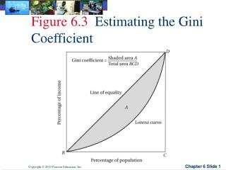
Eigenvalue analysis (natural frequencies). This is an input to the flutter analysis code. Lancair IV wing, mode 6, wing bending 14.77 Hz
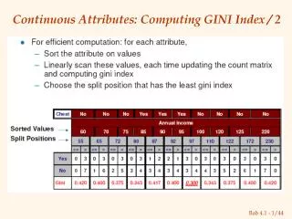
Finite element analysis of a CNC router table with heavy weight on it
Analysis results. Notice the exaggerated deformed shape. Max 0.00934” deformation.
Detailed design • 3D cad software will be employed throughout all the design phases. • To keep the cost down, a local, low cost NURBS modeler is used for generating the complex 3D surfaces, lofts and blend for the entire aircraft : Rhino 3D. • For detailed part and assembly design, control kinematics and fitting, a low cost 3D solid modeler, Alibre design will be used.
Manufacturing • No prototype. Straight cutting of plugs from CAD data. • Tooling making will be a very though job. • Precision CNC cut molds are required. • Very expensive to make. • Will use a self made, hobby grade 3 axis CNC router to cut the plugs. Maybe also a 4 axis (2x2) CNC hot wire cutter. • To cut costs, plugs will be made from a undersized, hot wire cut, polystyrene foam core, on top of which a 0.75”-1” thick layer of epoxy paste like Renpaste 4503 is applied, followed by curing and machining of the plug. • Plugs for big parts will need to be “indexed” in multiple subparts and then reassembled and glued due to lack of machining range for the CNC router. • After surface preparation of the plugs, the molds will be made using resin infusion out of a couple of layers carbon fiber, fiberglass and paste laminate core like FMSC 1020 to give the mold some thickness/rigidity. Care should be taken to select the right resins to withstand repetitive use in high temperature environment due to 250F/121°C curing of the prepregs. • Depending of the spar construction (unidirectional prepreg tape vs. Graphlite), the half wing can be oven cured together with the spar cap, otherwise, the spar cap needs to be manufactured separately. Vacuum bag method will be used. • Curing will be done in a “in house” made oven.
Oven curing • “In house” oven. I’m in the design phase now. • The goal is to make an aluminum or steel frame enclosure with 1” thick paper honeycomb panel walls (hexacomb) coated outside against humidity and inside having a very thin ceramic paper glued. Ceramic foam will be used on the inside edges for insulation.The enclosure will be easy and quick dismountable. • The heating source can be either electric kiln (70 KW requirement) or 2 home gas furnaces. • Temperature control can be done easily, with low cost commodity electronics and software.
Gluing, finishing, painting • Labor intensive. • Loctite aero line of composite adhesives. • Will use regular polyurethane painting. • Torayca T700 carbon fiber prepreg produce excellent finish out of the mold parts that require very little surface preparation • I’m investigating using surfacing films like Cytec’s Surface Master 905 that is applied first in the mold, followed by the prepregs. It eliminates sweep and fill operations and maybe application of paint primer. • A 1:10 prototype model using the same materials and production methods will be made first.
Suggestions are welcome, including: don’t even think about doing this...Or: stop dreaming…now !