Download
1 / 60
600 likes | 769 Vues
Critique of the Cranium. Chapter 9. PA and AP projection. Facility Identification Correct Marker Placement No Preventable Artifacts Correct Film Size. PA and AP projection. Contrast and density are adequate to demonstrates air-filled cavities and bony structures

E N D
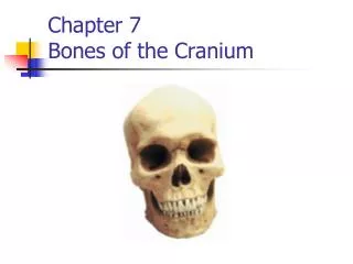
Critique of the Cranium Chapter 9
PA and AP projection • Facility Identification • Correct Marker Placement • No Preventable Artifacts • Correct Film Size
PA and AP projection • Contrast and density are adequate to demonstrates air-filled cavities and bony structures • Penetration is sufficient to demonstrate bony trabecular patterns and cortical outlines
PA and AP projection • True PA • The distances from the oblique orbital lines to the lateral cranial cortices are equal • The distance from the Crista galli to the lateral cranial cortices are equal
PA and AP projection • Detecting rotation • The patient’s face is rotated away from the side that exhibits the greatest distance between the Orbital rim and the lateral cortical border of the cranium
PA and AP projection • OML perpendicular to film • The petrous ridges should superimpose the supra orbital rims
PA projection • Evaluating OML position • If petrous ridges are below supra-orbital rim, the chin is too high (will look like a Caldwell view) • If petrous ridges are superior to the supra-orbital rim, the chin is too low.( will look like a Towne’s view)
AP trauma projection • Instead of moving head, angle central ray so that if forms a perpendicular angle with the OML • Evaluating OML position • If the petrous ridges are below the supra-orbital rim, angle tube more caudal • The central ray should be angled the way that you want the orbits to move.
PA and AP projection • The nasal septum and Crista galli should be aligned with the film and in the approximate center of the film
Caldwell Method (AP or PA) • Facility Identification • Correct Marker Placement • No Preventable Artifacts • Correct Film Size
Caldwell Method (AP or PA) • Contrast and density are adequate to demonstrates air-filled cavities and bony structures • Penetration is sufficient to demonstrate bony trabecular patterns and cortical outlines
Caldwell Method (AP or PA) • True PA • The distances from the oblique orbital lines to the lateral cranial cortices are equal • The distance from the Crista galli to the lateral cranial cortices are equal
Caldwell Method (AP or PA) • Detecting rotation • The patient’s face is rotated away from the side that exhibits the greatest distance between the Orbital rim and the lateral cortical border of the cranium
Caldwell Method (AP or PA) • If the angle between the OML and the film is perpendicular and the OML and the Central ray form a 15 degree angle, then • The petrous ridges should be projected through the lower 1/3 of the orbits.
Caldwell Method PA • If the petrous ridges are in the upper portion of the orbit,(1) the OML was not perpendicular to film or • (2)The OML and central ray did not form a 15 degree angle • (1) raise the chin • (2)increase angle
Caldwell Method PA • If the petrous ridges are inferior to the orbital rims,(1) the OML was not perpendicular to film or • (2)The OML and central ray did not form a 15 degree angle • (1) lower chin • (2) decrease angle
Caldwell PA • The petrous ridges move with the back of the head in the PA position • Raising chin moves petrous ridges down • Lowering chin moves petrous ridges up • Central ray moves the orbits, • Increasing angle moves orbits down • Decreasing angle moves orbits up
AP axial – Towne’s Position • Facility Identification • Correct Marker Placement • No Preventable Artifacts • Correct Film Size
AP axial – Towne’s Position • Contrast and density are adequate to demonstrates air-filled cavities and bony structures • Penetration is sufficient to demonstrate bony trabecular patterns and cortical outlines
AP axial – Towne’s Position • No rotation • The distances from the posterior clinoid process to the lateral borders of the foramen magnum on either side are equal • The petrous ridges are symmetrical • The dorsum sellae is centered within the foramen magnum
AP axial – Towne’s Position • The face is rotated toward the side of the patient which demonstrates the least amount of distance between the posterior clinoid processes and the lateral foramen magnum
AP axial – Towne’s Position • If the OML is perpendicular with the film and the CR is 30 degrees with the OML • The dorsum sellae and posterior clinoid are demonstrated within the foramen magnum without foreshortening or superimposing of the atlas’s posterior arch
AP axial – Towne’s Position • If dorsum sellae is projected inferior to the foramen magnum • The OML is not perpendicular with the film and the patient's chin is raised • Central ray needs to be increased
AP axial – Towne’s Position • If dorsum sellae is projected superior to the foramen magnum and superimposes the atlas's arch • The OML is not perpendicular with the film and the patient's chin is too low • Central ray needs to be decreased
AP axial – Towne’s Position • The sagittal suture and nasal septum are aligned with the long axis of the film • The inferior occipital bone is centered on the film • The outer cranial cortex, petrous ridges, dorsum sellae and foramen magnum are on the film
Lateral Positioncranium – facial bones - sinus • Facility Identification • Correct Marker Placement • No Preventable Artifacts • Correct Film Size
Lateral Positioncranium – facial bones - sinus • Contrast and density are adequate to demonstrates air-filled cavities and bony structures • Penetration is sufficient to demonstrate bony trabecular patterns and cortical outlines
Lateral Positioncranium – facial bones - sinus • True lateral • The sella turcica is demonstrated in profile • The orbital roofs, mandibular rami, greater wings of sphenoid, external auditory canals, and cranial cortices are superimposed
Lateral Positioncranium – facial bones - sinus • Detecting rotation • The sella turcica will e distorted • The mandibular rami, greater wings of sphenoid, EAC will be demonstrated anterior to one another.
Lateral Positioncranium – facial bones - sinus • Detecting tilt • The orbital roofs, greater wings of sphenoid, and EAC will appear superior to one another
Lateral Positioncranium • An area 2 inches above the EAM is in the center of the film
Lateral Positionfacial bones - sinus • The greater wings of sphenoid are in the center of the film
Submentovertex • Facility Identification • Correct Marker Placement • No Preventable Artifacts • Correct Film Size
Submentovertex • Contrast and density are adequate to demonstrates air-filled cavities and bony structures • Penetration is sufficient to demonstrate bony trabecular patterns and cortical outlines
Submentovertex • True SMV • IOML is parallel with image receptor • Mandibular mentum is demonstrated anterior to the ethmoid sinus • The distances between the mandibular rami and the cranial cortex on either side is equal
Submentovertex • If mandibular mentum lies to far anterior to ethmoid sinus • Head was tilted back to far • If mandibular mentum overlies ethmoid sinus • Head was not tilted enough • The most common error
Submentovertex • Detecting tilt • The distances between the mandibular rami and the outer cortex of the skull are not equal • The side that exhibits the greatest distance is the side that the cranial vertex is rotated toward
Submentovertex • The vomer and bony nasal septum are aligned with the long axis of the collimated field.
Submentovertex (basilar position) • The dens is in the center of the film
Submentovertex • The sphenoid sinuses are in the center of the film
SMV for Zygomatic arches • If right zygomatic arch is visalized, head is rotated toward the right • The head is rotated toward the side of interest
Parietoacanthal ProjectionWaters Position • Facility Identification • Correct Marker Placement • No Preventable Artifacts • Correct Film Size
Parietoacanthal ProjectionWaters Position • Contrast and density are adequate to demonstrates air-filled cavities and bony structures • Penetration is sufficient to demonstrate bony trabecular patterns and cortical outlines
Parietoacanthal ProjectionWaters Position • No rotation • The distances from the outer rim of the orbit to the outer cranial cortices are equal • The distance from the bony nasal septum to the lateral cranial cortex on either side are equal