Download
1 / 44
450 likes | 465 Vues
Overview of Fabrication Processes of MOSFETs and Layout Design Rules. There are very strong links between the fabrication process, the circuit design process and the performance of the resulting chip.

E N D
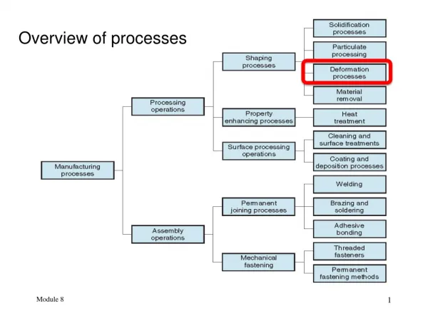
Overview of Fabrication Processes of MOSFETs andLayout Design Rules
There are very strong links between the fabrication process, the circuit design process and the performance of the resulting chip. Circuit designers must have a working knowledge of chip fabrication to create effective designs and to optimize the circuits with respect to various manufacturing parameters. Circuit designers must have a clear understanding of the roles of various masks used in the fabrication process, and how the masks are used to define various features of the devices on-chip.
Concentrate on the well-established CMOS fabrication technology Both n-channel (nMOS) and p-channel (pMOS) transistors be built on the same chip substrate To accommodate both nMOS and pMOS devices, special regions must be created in which the semiconductor type is opposite to the substrate type. These regions are called wells or tubs. In the simple n-well CMOS fabrication technology, the nMOS transistor is created in the p-type substrate, and the pMOS transistor is created in the n-well, which is built-in into the p-type substrate.
In the twin-tub CMOS technology, additional tubs of the same type as the substrate can also be created for device optimization. • starting with the creation of the n-well regions for pMOS transistors, by impurity implantation into the substrate. • A thick oxide is grown in the regions surrounding the nMOS and pMOS active regions. • The thin gate oxide is subsequently grown on the surface through thermal oxidation. • These steps are followed by the creation of n+ and p+ regions for source and drain conacts and by final metallization (creation of metal interconnects).
Simplified process sequence for fabrication of the n-well CMOS integrated circuit with a single polysilicon layer, showing only major fabrication steps
thermal oxidation of the silicon surface, by which an oxide layer of about 1 micrometer thickness, If the photoresist material is exposed to ultraviolet (UV) light, the exposed areas become soluble so that the they are no longer resistant to etching solvents. To selectively expose the photoresist, we have to cover some of the areas on the surface with a mask during exposure
initially insoluble and becomes soluble after exposure to UV light is called positive photoresist initially soluble and becomes insoluble (hardened) after exposure to UV light, called negative photoresist. The remaining photoresist can now be stripped from the silicon dioxide surface by using another solvent, leaving the patterned silicon dioxide feature on the surface as shown in Fig. 2.2(g).
Process flow for the fabrication of an n-type MOSFET on p-type silicon
fabrication sequence of n-well CMOS integrated circuits a top view of the lithographic masks and a cross-sectional view of the relevant areas.
Layout Design Rules layout design rules: The physical mask layout of any circuit must conform to a set of geometric constraints or rules, i.e. layout design rules These rules specify: the minimum allowable line widths such as metal and polysilicon interconnects or diffusion areas, minimum feature dimensions, and minimum allowable separations between two such features.
Layout Design Rules The main objective of design rules is to achieve a high overall yield and reliability while using the smallest possible silicon area, for any circuit to be manufactured with a particular process. The design rules are usually described in two ways Micron rules, minimum feature sizes and minimum allowable feature separations, are stated in terms of absolute dimensions in micrometers. Lambda rules, a single parameter () allow linear, proportional scaling of all geometrical constraints in terms of .
MOSIS Layout Design Rules (sample set) Rule number Description L-Rule R1 Minimum active area width 3 L R2 Minimum active area spacing 3 L R3 Minimum poly width 2 L R4 Minimum poly spacing 2 L R5 Minimum gate extension of poly over active 2 L R6 Minimum poly-active edge spacing 1 L (poly outside active area) R7 Minimum poly-active edge spacing 3 L (poly inside active area) R8 Minimum metal width 3 L R9 Minimum metal spacing 3 L
R10 Poly contact size 2 L R11 Minimum poly contact spacing 2 L R12 Minimum poly contact to poly edge spacing 1 L R13 Minimum poly contact to metal edge spacing 1 L R14 Minimum poly contact to active edge spacing 3 L R15 Active contact size 2 L R16 Minimum active contact spacing 2 L (on the same active region) R17 Minimum active contact to active edge spacing 1 L R18 Minimum active contact to metal edge spacing 1 L R19 Minimum active contact to poly edge spacing 3 L R20 Minimum active contact spacing 6 L (on different active regions)
Design rule constraints determine the dimensions of a minimum-size transistor
The initial phase of layout design can be simplified significantly by the use of stick diagrams - or so-called symbolic layouts. The detailed layout design rules are simply neglected and the main features (active areas, polysilicon lines, metal lines) are represented by constant width rectangles or simple sticks. The purpose of the stick diagram is to provide the designer a good understanding of the topological constraints, and to quickly test several possibilities for the optimum layout without actually drawing a complete mask diagram.
In the following, we will examine a series of stick diagrams which show different layout options for the CMOS inverter circuit.
Major steps required for generating the mask layout of a CMOS NOR2 gate
Major steps required for generating the mask layout of a CMOS NOR2 gate
Major steps required for generating the mask layout of a CMOS NOR2 gate
Stick diagram layout of the complex CMOS logic gate, with an arbitrary ordering of the polysilicon gate columns
The Euler path is defined as an uninterrupted path that traverses each edge (branch) of the graph exactly once
Notice that both the sum-circuit and the carry-circuit have been realized using one uninterrupted active area each