Download
1 / 27
270 likes | 273 Vues
The Selection of Manufacturing Engineering Processes. By Dr. Saied Darwish (Prof. Industrial Engineering Department, KSU). CONTENTS. CHAPTER ONE: Fits and Tolerances. CHAPTER TWO: Fundamental of metal cutting. CHAPTER THREE: Mechanics of metal cutting.

E N D
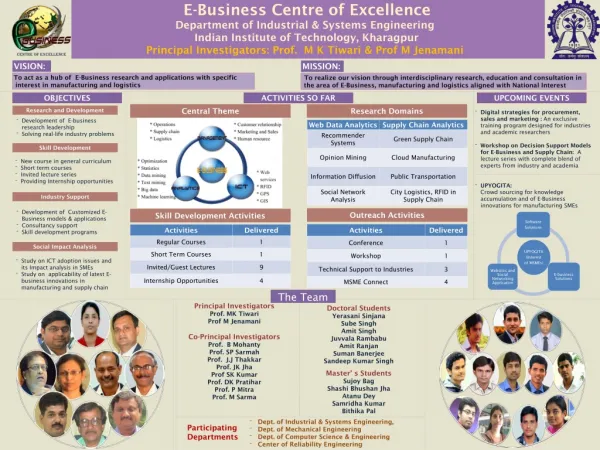
The Selection of Manufacturing Engineering Processes ByDr. Saied Darwish(Prof. Industrial Engineering Department, KSU)
CONTENTS CHAPTER ONE: Fits and Tolerances CHAPTER TWO: Fundamental of metal cutting CHAPTER THREE: Mechanics of metal cutting CHAPTER FOUR: Tool wear and tool life CHAPTER FIVE: Drilling CHAPTER SIX: Milling CHAPTER SEVEN : Grinding CHAPTER EIGHT: Broaching
CHAPTER SEVEN:Grinding Operation 7 CHAPTER SEVEN GRINDING OPERATION CONTENTS
CHAPTER SEVEN:Grinding Operation 7.1 Grinding operation Grinding is a material removal process in which abrasive particles are bonded to form a grinding wheel that operates at very high surface speeds. The grinding wheel is precisely balanced for high rotational speeds. Grinding may be linked to the milling process: Cutting occurs on either the periphery or the face of the grinding wheel, similar to peripheral milling and face milling. Figure 7.1
CHAPTER SEVEN:Grinding Operation Figure 7.1: (a) The geometry of surface grinding, showing cutting conditions; (b) assumed longitudinal shape and (c) cross-section of a single chip.
CHAPTER SEVEN:Grinding Operation 7.2 Significant differences between grinding and milling The abrasive grains in the wheel are much smaller than the teeth on the milling cutter. Cutting speeds in grinding are much higher than in milling. A grinding wheel is self sharpening (as the wheel wears, the abrasive particles become dull and either fracture to create fresh cutting edges or are pulled out of the surface of the wheel to expose new grains).
CHAPTER SEVEN:Grinding Operation 7.3 The grinding wheel The grinding wheel consists of abrasive particles and bonding materials. The bonding material holds particles in place and establishes the structure and shape of the wheel.
CHAPTER SEVEN:Grinding Operation 7.4 Abrasive material General properties of an abrasive material used in grinding wheels include high hardness, wear resistance, and toughness. The abrasive materials of greatest commercial importance are: Aluminum oxide (Al2O3) Silicon carbide (SiCa) Cubic boron nitride (CBN) Diamond (natural and synthetic)
CHAPTER SEVEN:Grinding Operation 7.5 Grain size There are two main grain sizes available: Small grain size: suitable for grinding hard materials, with better surface finish. Large grain size is suitable for grinding soft materials with high material removal rate.
CHAPTER SEVEN:Grinding Operation 7.6 Bonding materials The bonding material must be able to withstand centrifugal forces and high temperatures. Following are some common bonding materials: Vitrified bond (clay and ceramic materials) Silicate bond (sodium silicate) Rubber bond Metallic bond (usual bond)
CHAPTER SEVEN:Grinding Operation 7.6 Cont. Bonding materials
CHAPTER SEVEN:Grinding Operation 7.7 Standard grinding wheel shapes Grinding wheels are available in different shapes, in figure some standard grinding wheel shapes are shown. Figure 7.2: Some standard grinding wheel shapes: (a) straight, (b) recessed two sides, (c) metal wheel frame with abrasive bonded to outside circumference, (d) abrasive cutoff wheel, (e) cylinder wheel, (f) straight cup wheel, and (g) flaring cup wheel
CHAPTER SEVEN:Grinding Operation 7.8 Dressing of grinding wheel As the wheel is used, there is a tendency for the wheel to become loaded with metallic chips and the grains become dull or glaze. To improve the condition of the wheel a process termed “wheel dressing” is used as shown in figure 7.3. Figure7.3: Schematic arrangement of stick dressing.
CHAPTER SEVEN:Grinding Operation 7.9 Truing of grinding wheel Grinding wheels lose their geometry during use. Truing operation restores the original shape. A single point diamond tool is used to true the wheel as shown in figure 7.4. Figure 7.4: Diamond nibs may be used for truing wheels in batch operations
CHAPTER SEVEN:Grinding Operation 7.10 Grinding operations and grinding machines 7.10.1 Cylindrical grinding: Cylindrical grinding as its name suggests, is used for rotational parts. These grinding operations are divided into two basic types. External cylindrical grinding which is similar to external turning. The grinding machine used for these operations closely resemble a lathe in which the tool post has been replaced by a high speed motor to rotate the grinding wheel. Internal cylindrical grinding operates somewhat like a boring operation. The workpiece is usually held in a chuck and rotated to provide surface speed. The wheel is fed in either of two ways: (1) traverse feed or (2) plunge feed
CHAPTER SEVEN:Grinding Operation Figure 7.5: Two types of cylindrical grinding: (a) external and (b) internal
CHAPTER SEVEN:Grinding Operation 7.10 Grinding operations and grinding machines 7.10.1 Cylindrical grinding: traverse feed: grinding wheel is fed in a direction parallel to the axis of rotation of the workpiece plunge feed: plunge cut, the grinding wheel is fed radially into the work
CHAPTER SEVEN:Grinding Operation Figure 7.6: Two types of feed motion in external cylindrical: (a) traverse feed and (b) plunge-cut.
CHAPTER SEVEN:Grinding Operation 7.10.2 Surface grinding Surface grinding is normally used to grind plain flat surfaces. It is performed using either the periphery of the grinding wheel or the flat face of the wheel. Four types of surface grinding machines are used in surface grinding operation. horizontal spindle with reciprocating worktable horizontal spindle with rotating worktable vertical spindle with reciprocating worktable vertical spindle with rotating worktable.
CHAPTER SEVEN:Grinding Operation Figure 7.7: Four types of surface grinding: (a) horizontal spindle with reciprocating worktable, (b) horizontal spindle with rotating worktable, (c) vertical spindle with reciprocating worktable, and (d) vertical spindle with rotating worktable.
CHAPTER SEVEN:Grinding Operation 7.10.3 Centerless grinding Centerlessgrinding has a number of advantages over cylindrical grinding. It is self-centering, the stock removal rate is higher, and the work is firmly held by the support plate and control or regulating wheel, which results in better dimensional accuracy Figure 7.8: External centerless grinding
CHAPTER SEVEN:Grinding Operation Figure 7.9: Internal centerless grinding.
CHAPTER SEVEN:Grinding Operation 7.11 Forces and power in grinding There are three force components involved in the grinding operation Pr= Radial force, Pa = Axial force, Ps = Main cutting force (Tangential force). The power can be calculated from the following formula. (kW) Figure 7.10: Force components in grinding.
CHAPTER SEVEN:Grinding Operation 7.12 Related abrasive processes 7.12.1 Honing Honing is an abrasive process performed by a set of bonded abrasive sticks. A common application is to finish the bores of internal combustion engines, other applications Figure 7.11: The honing process: (a) the honing tool used for internal bore surfaces (b) cross hatched surface pattern created by the action of the honing tool.
CHAPTER SEVEN:Grinding Operation 7.12.2 Lapping Lapping is an abrasive process used to produce surface finish of extreme accuracy and smoothness. It is used in the production of optical lenses, metallic bearing surfaces and gauges Figure 7.12: The lapping process in lens making.
CHAPTER SEVEN:Grinding Operation 7.12.3 Super finishing Super finishing is an abrasive process similar to honing. Super finishing differ from honing in the following aspects: The strokes are shorter. High frequencies are used. Lower pressure is applied between the tool and surface. The grit size are smaller. Workpiece speed is slower.
CHAPTER SEVEN:Grinding Operation The result of these conditions is mirror like finishes. This process can be used to finish flat and external cylindrical surfaces, as shown in figure 7.13. Figure 7.13: Super finishing on an external cylindrical surface.