Download
1 / 30
310 likes | 540 Vues
Double Data Rate SDRAM – The Next Generation. An overview of the industry roadmap for main system memory technology, and details on DDR which represents the latest state of the art for SDRAM. We will cover: The industry standards process for product definition The evolution of main memories

E N D
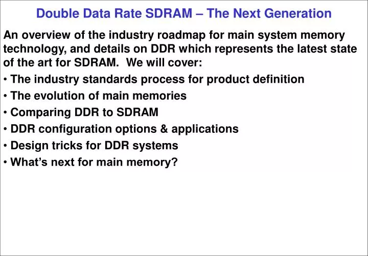
Double Data Rate SDRAM – The Next Generation An overview of the industry roadmap for main system memory technology, and details on DDR which represents the latest state of the art for SDRAM. We will cover: • The industry standards process for product definition • The evolution of main memories • Comparing DDR to SDRAM • DDR configuration options & applications • Design tricks for DDR systems • What’s next for main memory?
The JEDEC Standards Process • JEDEC is a non-profit standards organization • 265 member companies from all over the world • Suppliers & users and even competitors • Working together to expand the market
How standards get done • Any company presents a market need • Interested companies form a Task Group • TG does development, submits ballot to committee • Feedback from voting incorporated into spec • The new standard is published • Task Group reforms as needed for enhancements
Main Memory DRAM Evolution SDRAM EDO FP 4800MB/s MainstreamMemories DDR II 2100MB/s DDR 1000MB/s 400MB/s Simple,incrementalsteps 320MB/s
Cost remains constant • The top three factors driving memory evolution • Cost • Cost • Cost • The price of memory has remained essentially constant • Each incremental enhancement must “come for free” • “Free” means similar evolution of costs: • Direct: die size, packaging, testers, licensing • Indirect: PCB complexity, heat sinks, support components • 2x indirect: dummy continuity boards
What is DDR? • Internally, DDR is an SDRAM with ping pong registers • Data is posted on rising and falling edges of the clock • Commands still sampled on rising edge
How Different is DDR? • Simple upgrade from SDRAM designs • Same PCB characteristics: 60 6 • Same RAS/CAS command set • A few evolutionary improvements • Low voltage swing I/O • Differential clocks • Source synchronous data strobe
DDR low voltage signaling • SSTL_2 low voltage swing inputs • 2.5V I/O with 1.25V reference voltage • Low voltage swing with termination • Rail to rail if unterminated DDR
DDR Differential Clocks • Route differential clocks on adjacent traces • Timing is relative to crosspoint • Helps insure 50% duty cycle
DDR Read Timing – Data delivered on both edges of CK • Data valid on rising & falling edges • Data Strobe “DQS” travels with data • DLL aligns data to clock edges
Emphasis on “Matched” CONTROLLER DDR SDRAM DQ/DQS VREF VREF DM VREF VREF Disable • DM/DQS loading identical to DQ • Route as independent 8 bit buses
Combining 8 bit buses into internal bus width DQS DQ DQS DQS DQ DQ • Each byte samples using DQS as input strobe • Input buffers capture one odd and one even byte • Commit to FIFO on controller clock DM DM DM 8 8 8 Clocked in memory time domain Internal Memory FIFO Clocked in controller time domain
DDR Configurations DIMM TSOP TQFP SO-DIMM
DDR Configurations, Chips • 66 pin TSOP-II • Inexpensive high volume plastic package • Compatible pinout for X4, X8, X16 • 64Mb to 512Mb; 1Gb in development • 100 pin TQFP • Inexpensive high volume plastic package • X32 configuration • 64Mb and 128Mb
DDR Configurations, Modules • Desktop & Server 184 pins, 5.25” long X64 or X72 (ECC) 64MB to 2GB Mobile & Small Form FactorÞ • 200 pins, 2.7” long • X64 or X72 (ECC) • 32MB to 512MB
DDR Unbuffered DIMM • Least expensive module • Limits number of loads supportable • Address bus hits all DDR SDRAMs • Fastest access time DDRSDRAM DDRSDRAM DDRSDRAM DDRSDRAM Data Data Address Data Data
DDR Registered DIMM • Doubles density of each module orhalves number of address buses needed • Address bus latched before going to DDR SDRAMs • Access time increased by one clock DDRSDRAM DDRSDRAM DDRSDRAM DDRSDRAM Register Data Data Address Data Data
Power Management RelativePower CPU Clocks of Latency** Active on PowerState* 100% 4% 12% 0 * 5 = 0 Inactive on 3 * 5 = 15 Active off 1 * 5 = 5 Inactive off 0.2% 4 * 5 = 20 OpenPage * Not industry standard terms – simplified for brevity **Assumes 5 CPU clocks per memory clock Sleep ClosedPage 0.4% 200*5 = 1000
Power: DDR vs SDRAM DDR-266 3X DDR-333 2.6X (est) PC-100 1X PC-133 0.8X
Next: Enhancing DDR from 266 to 333 MHz data rate • Qualification of DDR333 under way • Possibly different DDR SDRAM packages for each solution: • Unbuffered DIMM: FBGA • Registered DIMM: TSOP • SO-DIMM: TSOP • Point to point: TSOP
Next: Small Packages FBGA • Lower inductance • Lower capacitance • Smaller footprint • Tighter layouts enabled Details: Package size = 104 mm2 = 54% smaller Inductance: 1.7nH lower Inductance variation, pin to pin: 3X less Capacitance: 0.5pF lower Performance gain: 300ps of data valid time
Next: DDR FET Switched DIMM • Quadruples density of each module ordoubles number of DIMM slots • Address bus latched before going to DDR SDRAMs • Data bus sees a single load per slot • Additional bus turnaround latency DDRSDRAM DDRSDRAM DDRSDRAM DDRSDRAM Register FET FET FET FET Data Data Address Data Data
Next: DDR MicroDIMM • Half the size of the DDR SO-DIMM • Half the capacity if using TSOP – or – • Same capacity if using FBGA • Target markets: • PDAs • Internet appliances • Subnotebook computers
Next: DDR II • Work well under way on DDR II • Double the speed • Lower power • Migration path from DDR I • Same controller can use DDR I and DDR II • Compatible process technologies
Conclusions • DDR is a result of collaboration between many companies • Cost drives incremental evolutionary steps • DDR is a simple evolution of SDRAM technology • Configuration options available for different applications • Use tricks and techniques to exploit DDR’s features • The future of DDR is in evolutionary steps