Download
1 / 59
590 likes | 713 Vues
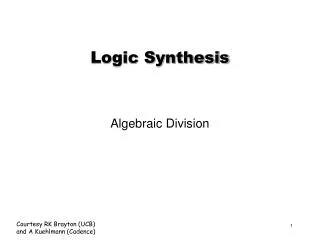
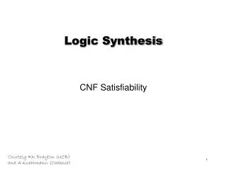
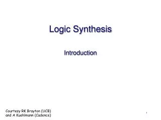
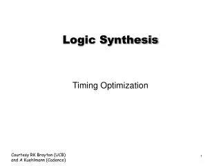
Logic synthesis from concurrent specifications. Jordi Cortadella Universitat Politecnica de Catalunya Barcelona, Spain. In collaboration with M. Kishinevsky, A. Kondratyev, L. Lavagno and A. Yakovlev. Outline. Overview of the synthesis flow Specification

E N D
Logic synthesis from concurrent specifications Jordi Cortadella Universitat Politecnica de CatalunyaBarcelona, Spain In collaboration with M. Kishinevsky, A. Kondratyev, L. Lavagno and A. Yakovlev
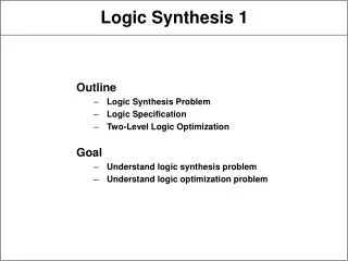
Outline • Overview of the synthesis flow • Specification • State graph and next-state functions • State encoding • Implementability conditions • Speed-independent circuit • Complex gates • C-element architecture • Review of some advanced topics
Book and synthesis tool • J. Cortadella, M. Kishinevsky, A. Kondratyev,L. Lavagno and A. Yakovlev,Logic synthesis for asynchronouscontrollers and interfaces,Springer-Verlag, 2002 • petrify:http://www.lsi.upc.es/petrify
Design flow Specification(STG) Reachability analysis State Graph State encoding SG withCSC Boolean minimization Next-state functions Logic decomposition Decomposed functions Technology mapping Gate netlist
Specification x x y y z z z+ x- x+ y+ z- y- Signal Transition Graph (STG)
x y z z+ x- x+ y+ z- y- Token flow
xyz 000 x+ 100 y+ z+ z+ x- 110 101 x- x+ y+ z- y- y+ z+ 001 111 y- y+ x- 011 z- 010 State graph
xyz 000 x+ 100 y+ z+ 110 101 x- y- y+ z+ 001 111 y+ x- 011 z- 010 Next-state functions
Gate netlist x y z
Design flow Specification(STG) Reachability analysis State Graph State encoding SG withCSC Boolean minimization Next-state functions Logic decomposition Decomposed functions Technology mapping Gate netlist
DSr LDS LDTACK D DTACK Read Cycle VME bus Bus Data Transceiver Device D DSr LDS VME Bus Controller DSw LDTACK DTACK
STG for the READ cycle DSr+ DTACK- LDS+ LDTACK+ D+ DTACK+ DSr- D- LDTACK- LDS- D LDS DSr VME Bus Controller LDTACK DTACK
LDTACK- DTACK- DTACK- LDTACK- LDS- LDS- Choice: Read and Write cycles DSr+ DSw+ LDS+ D+ LDTACK+ LDS+ D+ LDTACK+ DTACK+ D- DSr- DTACK+ D- DSw-
DTACK- DSr+ DSw+ LDS+ D+ LDTACK+ LDS+ LDTACK- D+ LDTACK+ DTACK+ D- LDS- DSr- DTACK+ D- DSw- Choice: Read and Write cycles
Circuitsynthesis • Goal: • Derive a hazard-free circuitunder a given delay model andmode of operation
Speed independence • Delay model • Unbounded gate / environment delays • Certain wire delays shorter than certain paths in the circuit • Conditions for implementability: • Consistency • Complete State Coding • Persistency
Design flow Specification(STG) Reachability analysis State Graph State encoding SG withCSC Boolean minimization Next-state functions Logic decomposition Decomposed functions Technology mapping Gate netlist
STG for the READ cycle DSr+ DTACK- LDS+ LDTACK+ D+ DTACK+ DSr- D- LDTACK- LDS- D LDS DSr VME Bus Controller LDTACK DTACK
LDS + LDS = 0 LDS - LDS = 1 Binary encoding of signals DSr+ DTACK- LDS+ LDTACK- LDTACK- LDTACK- DSr+ DTACK- LDS- LDS- LDS- LDTACK+ DSr+ DTACK- D+ D- DTACK+ DSr-
01100 00110 Binary encoding of signals 10000 DSr+ DTACK- LDS+ LDTACK- LDTACK- LDTACK- DSr+ DTACK- 10010 LDS- LDS- LDS- LDTACK+ DSr+ DTACK- 10110 01110 10110 D+ D- DTACK+ DSr- (DSr , DTACK , LDTACK , LDS , D)
ER (LDS+) LDS+ QR (LDS-) LDS- LDS- LDS- ER (LDS-) QR (LDS+) Excitation / Quiescent Regions
LDS+ LDS- LDS- LDS- 10110 10110 Next-state function 0 1 0 0 1 1 1 0
DTACK DSr DTACK DSr D LDTACK D LDTACK 00 00 01 01 11 11 10 10 00 00 01 01 11 11 10 10 Karnaugh map for LDS LDS = 1 LDS = 0 - - - 0 0 - 1 1 - - - - - - - - 1 1 1 - - - - - 0 0 - 0 0 0 - 0/1?
Design flow Specification(STG) Reachability analysis State Graph State encoding SG withCSC Boolean minimization Next-state functions Logic decomposition Decomposed functions Technology mapping Gate netlist
DSr+ DSr+ DSr+ Concurrency reduction LDS+ LDS- LDS- LDS- 10110 10110
Concurrency reduction DSr+ DTACK- LDS+ LDTACK+ D+ DTACK+ DSr- D- LDTACK- LDS-
State encoding conflicts LDS+ LDTACK- LDS- LDTACK+ 10110 10110
CSC+ CSC- Signal Insertion LDS+ LDTACK- LDS- LDTACK+ 101101 101100 D- DSr-
Design flow Specification(STG) Reachability analysis State Graph State encoding SG withCSC Boolean minimization Next-state functions Logic decomposition Decomposed functions Technology mapping Gate netlist
Implementability conditions • Consistency • Rising and falling transitions of each signal alternate in any trace • Complete state coding (CSC) • Next-state functions correctly defined • Persistency • No event can be disabled by another event (unless they are both inputs)
Implementability conditions • Consistency + CSC + persistency • There exists a speed-independent circuit that implements the behavior of the STG(under the assumption that ay Boolean function can be implemented with one complex gate)
a- c+ a 100 000 001 b c b+ b+ Persistency a c b is this a pulse ? Speed independence glitch-free output behavior under any delay
a+ 0000 a+ b+ 1000 b+ 1100 a- a- 0100 c+ c+ 0110 d+ d- d+ 0111 a+ a+ 1111 b- b- 1011 a- c- a- c- 0011 1001 a- c- d- 0001
ab 0000 cd 00 01 11 10 a+ 1000 0 0 0 0 00 b+ 1100 1 0 a- 01 0100 c+ 1 1 1 1 0110 11 d- d+ 0111 1 10 a+ 1111 b- 1011 a- c- 0011 1001 a- c- 0001 ER(d+) ER(d-)
0000 a+ 1000 b+ 1100 a- 0100 c+ 0110 d- d+ 0111 a+ 1111 b- 1011 a- c- 0011 1001 a- c- 0001 ab cd 00 01 11 10 0 0 0 0 00 1 0 01 1 1 1 1 11 1 10 Complex gate
S z C R Implementation with C elements • • • S+ z+ S- R+ z- R- • • • • S (set) and R (reset) must be mutually exclusive • S must cover ER(z+) and must not intersect ER(z-) QR(z-) • R must cover ER(z-) and must not intersect ER(z+) QR(z+)
0000 a+ 1000 b+ 1100 a- 0100 c+ 0110 d- d+ 0111 a+ 1111 b- 1011 a- c- 0011 1001 a- c- 0001 ab cd 00 01 11 10 0 0 0 0 00 1 0 01 1 1 1 1 11 1 10 S d C R
0000 a+ 1000 b+ 1100 a- 0100 c+ 0110 d- d+ 0111 a+ 1111 b- 1011 a- c- 0011 1001 a- c- 0001 ab cd 00 01 11 10 0 0 0 0 00 1 0 01 1 1 1 1 11 1 10 S d C R Monotonic covers
C-based implementations S c d d C C R b a c weak c d weak d a a b generalized C elements (gC)
Speed-independent implementations • Implementability conditions • Consistency • Complete state coding • Persistency • Circuit architectures • Complex (hazard-free) gates • C elements with monotonic covers • ...
y- y- 1001 z- w- 1000 0001 w+ y+ w- z- x+ z- w- w+ 1010 0000 0101 w- y+ x+ z- y+ x+ x- 0010 0100 x- x+ y+ z+ 0110 z+ Synthesis exercise 1011 0011 0111 Derive circuits for signals x and z (complex gates and monotonic covers)
y- 1001 z- w- 1000 0001 w+ y+ w- z- x+ 1010 0000 0101 w- y+ x+ z- 0010 0100 x- x+ y+ z+ 0110 Synthesis exercise 1011 wx yz 00 01 11 10 - 1 0 1 00 0011 - 1 0 1 01 - 0 0 0 11 - 1 1 0 10 0111 Signal x
y- 1001 z- w- 1000 0001 w+ y+ w- z- x+ 1010 0000 0101 w- y+ x+ z- 0010 0100 x- x+ y+ z+ 0110 Synthesis exercise 1011 wx yz 00 01 11 10 - 0 0 0 00 0011 - 0 0 0 01 - 1 1 1 11 - 1 0 0 10 0111 Signal z
Logic decomposition: example y- y- 1001 1011 z- w- 1000 0001 w+ y+ w- z- x+ z- w- w+ 1010 0000 0101 0011 w- y+ x+ z- y+ x+ x- 0010 0100 x- x+ y+ z+ 0110 0111 z+
y- 1001 1011 z- w- 1000 0001 w+ y+ w- z- x+ 1010 0000 0101 0011 w- y+ x+ z- C 0010 0100 x- x+ y+ z+ C 0110 0111 yz=0 yz=1 Logic decomposition: example x y- y w 1001 1011 z- z w- y 1000 0001 w+ y+ z w- z- x+ x w 1010 0000 0101 0011 w- y+ x+ z- w z y 0010 0100 x- z x+ y+ z+ y 0110 0111 x z y
C C Logic decomposition: example s=1 x y- w s 1001 1011 y z- s- z w+ 1001 1000 z- s- y+ w- x w 0011 1000 0001 1010 y+ s- w- z- x+ w x- z y 1010 0000 0101 z w- y+ x+ z- 0111 0010 0100 y s+ x+ y+ x z s=0 z+ 0111 y 0110
Logic decomposition: example s=1 y- y- 1001 1011 z- s- s- w+ 1001 1000 z- s- y+ w- z- w- w+ 0011 1000 0001 1010 y+ s- w- z- x+ x- 1010 0000 0101 y+ x+ x- w- y+ x+ z- 0111 0010 0100 s+ s+ x+ y+ z+ s=0 z+ 0111 0110
Speed-independent Netlist DSr+ DTACK- LDS+ LDTACK+ D+ DTACK+ DSr- D- LDTACK- LDS- D DTACK LDS map csc DSr LDTACK
LDTACK- before DSr+ SLOW FAST Adding timing assumptions DSr+ DTACK- LDS+ LDTACK+ D+ DTACK+ DSr- D- LDTACK- LDS- D DTACK LDS map csc DSr LDTACK