Download
1 / 33
330 likes | 450 Vues
Mitigation of parallel RF potentials by an appropriate antenna design using TOPICA. R. Maggiora and D. Milanesio. Special thanks to ENEA. ASDEX Upgrade and CYCLE teams. Outline. Motivations and background ITER-like IC antenna ASDEX Upgrade IC antenna Plasma sensitivity Conclusions.

E N D
Mitigation of parallel RF potentials by an appropriate antenna design using TOPICA R. Maggiora and D. Milanesio Special thanks to ENEA. ASDEX Upgrade and CYCLE teams
Outline Motivations and background ITER-like IC antenna ASDEX Upgrade IC antenna Plasma sensitivity Conclusions
Motivations and background The successful design of an IC antenna is based not only on the capability to deliver enough power to the plasma (feature that has been extensively investigated in recent years), but also on the reduction of those unwanted phenomena, such as rectification discharges or hot spots, that are naturally associated with the required power levels. In these conditions, an accurate design tool such as TOPICA, i.e. able to account for a realistic 3D antenna geometry and an accurate plasma model, is essential!
Outline Motivations and background ITER-like IC antenna ASDEX Upgrade IC antenna Plasma sensitivity Conclusions
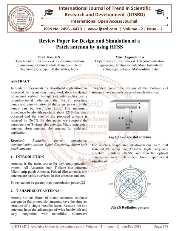
Realistic ITER-like antenna geometry based on 2010 TOPICA model, not tilted FS • Electric field computed at the plasma edge, located at constant 5mm distance from the FS • Constant 4cm distance between the straps and the plasma edge • 2cm gap all around the antenna box to account for the grounding, located 1m in the back TOPICA modeling: reference geometry • Full horizontal septa • “V-shaped” curvature in the poloidal direction only • Constant plasma profile: Sc2short (~17cm SOL), Bangle=15° • Constant working frequency: 53MHz
Realistic ITER-like antenna geometry based on 2010 TOPICA model, not tilted FS • Electric field computed at the plasma edge, located at constant 5mm distance from the FS • Constant 4cm distance between the straps and the plasma edge • 2cm gap all around the antenna box to account for the grounding, located 1m in the back TOPICA modeling: retracted horizontal septa • Fully retracted (4cm) top and bottom horizontal septa • “V-shaped” curvature in the poloidal direction only • Constant plasma profile: Sc2short (~17cm SOL), Bangle=15° • Constant working frequency: 53MHz
TOPICA modeling: retracted horizontal septa Top and bottom horizontal septa have been retracted of 4cm respect to the their original position in the reference geometry The horizontal central septum has not been moved at this stage Reference geometry
RF potentials: retracted horizontal septa 20MW coupled to plasma Tilted magnetic field lines (15°) RF potentials are shown 5mm in front of FS bars Poloidal phasing: 0π RF potentials strongly depend on the input phasing. Visible reduction localized on the magnetic lines crossing the upper and lower horizontal septa Lower horizontal septum 8
Realistic ITER-like antenna geometry based on 2010 TOPICA model, tilted FS according to magnetic field lines • Electric field computed at the plasma edge, located at constant 5mm distance from the FS • Constant 4cm distance between the straps and the plasma edge • 2cm gap all around the antenna box to account for the grounding, located 1m in the back TOPICA modeling: tilted FS bars • Full horizontal septa • “V-shaped” curvature in the poloidal direction only • Constant plasma profile: Sc2short (~17cm SOL), Bangle=15° • Constant working frequency: 53MHz
RF potentials: tilted FS bars 20MW coupled to plasma Tilted magnetic field lines (15°) RF potentials are shown 5mm in front of FS bars Poloidal phasing: 0π Remarkable reduction of RF potentials on the entire poloidal section Power coupled to plasma is 15% lower 10
RF potentials: tilted FS bars & fields misalignment 20MW coupled to plasma Tilted magnetic field lines (15°) RF potentials are shown 5mm in front of FS bars Poloidal phasing: 0π Field misalignment could determine, depending on the poloidal position, a not negligible increase of the RF potentials 11
RF potentials: tilted antenna 20MW coupled to plasma Tilted magnetic field lines (15°) RF potentials are shown 5mm in front of FS bars Poloidal phasing: 0π The alignment of the whole antenna to B (instead of the FS alone) remarkably reduces the RF potentials for 0ππ0 toroidal phasing, i.e. in case of symmetrical feeding 12
Outline Motivations and background ITER-like IC antenna ASDEX Upgrade IC antenna Plasma sensitivity Conclusions
TOPICA modeling: reference geometry • Approximated flat model based on the “reference” ASDEX Upgrade IC antenna recently installed • Constant working frequency: 30MHz • Constant 4.5cm distance between the straps and the plasma edge • Two plasma profiles: a small gap and a large gap measured in 2010 campains • Electric field computed 3mm in front of the limiters
The “broader limiter” approach Broader limiters Radial plates Return currents are induced on the two lateral radial plates and then screened by the FS bars Tapered straps
Plasma1 (small gap) 1MW coupled to plasma Tilted magnetic field lines (11°) Reference antenna BL antenna Average reduction (global) Plasma1 : 1.85 Plasma2 : 1.59 Average reduction (local) Plasma1 : 2.09 Plasma2 : 1.88 Peak reduction Plasma1 : 1.77 Plasma2 : 2.56 Reference vs. Broader Limiter Plasma2 (large gap)
Broader limiter Radial plate An alternative approach Tapered simpler straps Recessed horizontal limiter (to FS level) The basic concept is to have a two-layers recess to protect the back connections to the straps and to exploit all the possible symmetries in the plasma facing components. Two-layers concept
Plasma1 (small gap) 1MW coupled to plasma Tilted magnetic field lines (11°) Reference antenna BL antenna Alternative design Average reduction (global) Plasma1 : 2.89 (1.85) Plasma2 : 2.63 (1.59) Average reduction (local) Plasma1 : 4.20 (2.09) Plasma2 : 3.65 (1.88) Peak reduction Plasma1 : 18.39 (1.77) Plasma2 : 7.63 (2.56) An alternative approach Plasma2 (large gap) BL antenna Substantial RF potential reduction despite slightly higher absolute electric field.
Are flat models a reliable approximation of the real curved geometries, both in terms of coupled power and RF potentials? Milanesio D. et Al. - “Analysis of the impact of antenna and plasma models on RF potentials evaluation” poster session B31 Do the differences between flat models hold true also for curved geometries? Krivska A. et Al. - “Density profile sensitivity study of ASDEX Upgrade ICRF Antennas with the TOPICA code” poster session A55 To be continued … Are 3 straps or 4 straps geometries better than the 2 straps solutions? Come and check it at the poster session!
Outline Motivations and background ITER-like IC antenna ASDEX Upgrade IC antenna Plasma sensitivity Conclusions
Cutoff density Antenna position Cutoff density Plasma sensitivity Antenna position The plasma sensitivity is tested for a number of plasma profiles (varying the density gradient and the antenna-cutoff distance) both in terms of power transferred to plasma and of RF potentials
Cutoff density Antenna position 2cm vacuum layer Cutoff density Plasma sensitivity Antenna position The plasma sensitivity is tested for a number of plasma profiles (varying the density gradient and the antenna-cutoff distance) both in terms of power transferred to plasma and of RF potentials
Cutoff density Antenna position 4cm vacuum layer Cutoff density Plasma sensitivity Antenna position The plasma sensitivity is tested for a number of plasma profiles (varying the density gradient and the antenna-cutoff distance) both in terms of power transferred to plasma and of RF potentials
Cutoff density Antenna position 4cm vacuum layer Cutoff density Plasma sensitivity Antenna position The plasma sensitivity is tested for a number of plasma profiles (varying the density gradient and the antenna-cutoff distance) both in terms of power transferred to plasma and of RF potentials
1MW coupled to plasma Tilted magnetic field lines (11°) No vacuum Test3a 2cm vacuum Test2a Test1a Plasma sensitivity: density gradient Provided the same antenna-cutoff distance, a negligible dependence on the density gradient is observed 4cm vacuum 25
1MW coupled to plasma Tilted magnetic field lines (11°) 4cm vacuum No vacuum Test3a Test2a Test1a Plasma sensitivity: antenna-cutoff distance Provided the same density gradient, the RF potentials notably increase with a vacuum layer insertion 26
Vacuum vs. full plasma profile 1MW coupled to plasma Tilted magnetic field lines (11°) Antenna position Cutoff density The RF potentials are considerably different if, instead of adding a vacuum layer, a full plasma profile is loaded Effect of the slow wave…
1MW coupled to plasma Tilted magnetic field lines (11°) Plasma sensitivity: edge density Cutoff density Antenna position Provided the same core-cutoff density profile, the increase of the edge density determines an RF potentials reduction 28
Outline Motivations and background ITER-like IC antenna ASDEX Upgrade IC antenna Plasma sensitivity Conclusions
Conclusions • Localized modifications of the geometry can be rather effective in terms of RF potentials mitigation. As a consequence, the precise knowledge of the antenna geometry (in particular of the front part) is mandatory to carefully predict the electric field distribution in front of it and, therefore, to compute the RF potentials. • At least two approaches can be pursued to reduce RF potentials, i.e. to lower the electric fields absolute value and to reduce geometrical asymmetries. • A plasma loading should be adopted in order to be as realistic as possible. Moreover, a parametric study of the plasma profile (above all of the SOL) is extremely important to provide accurate predictions. • Is there a perfect antenna? • Retracted horizontal septa • A Bangle tilted antenna and FS • A toroidally symmetric antenna • Additional feeding lines with phase and amplitude flexibility
ε=81+2400i 1MW coupled to plasma Tilted magnetic field lines (11°) Reference antenna BL antenna Average reduction (global) Dielectric : 2.19 Plasma1 : 1.85 Plasma2 : 1.59 Average reduction (local) Dielectric : 2.89 Plasma1 : 2.09 Plasma2 : 1.88 Peak reduction Dielectric : 1.71 Plasma1 : 1.77 Plasma2 : 2.56 Plasma1 (small gap) Reference vs. Broader Limiter Plasma2 (large gap)
Plasma1 (small gap) Plasma1 (small gap) Reference antenna BL antenna Alternative design Plasma2 (large gap) Plasma2 (large gap) An alternative approach Average reduction (global) Plasma1 : 2.89 (1.85) Plasma2 : 2.63 (1.59) Peak reduction Plasma1 : 18.39 (1.77) Plasma2 : 7.63 (2.56) 1MW coupled to plasma Tilted magnetic field lines (11°) Substantial RF potential reduction despite the higher total electric field. BL antenna