Download
1 / 52
520 likes | 635 Vues
IEEE 802.1D: Spanning Tree Algorithm and the Filtering Database. Ben Schultz Bridge Functions Consortium UNH InterOperability Lab July, 2000. Presentation Overview. Filtering Database general concepts history the learning Bridge. Presentation Overview. Spanning Tree Algorithm

E N D
IEEE 802.1D: Spanning Tree Algorithm and the Filtering Database Ben Schultz Bridge Functions Consortium UNH InterOperability Lab July, 2000
Presentation Overview Filtering Database • general concepts • history • the learning Bridge
Presentation Overview Spanning Tree Algorithm • general concepts • overview of procedures • operation at bridge boot time • operation during LAN topology reconfiguration
Bridging: The Filtering Database • The Transparent Bridge • history and alternatives • the learning bridge • how this relates to VLANs and the spanning tree algorithm
Some terms before we start. • LAN: Local Area Network. • It could be a ring (in the sense of Token Ring or FDDI). • It could be a shared network (such as legacy or repeated Ethernet). • It could be a point to point link (like full duplex Ethernet)
More terms • Bridge: a layer 2 device that allows 2 separate LANs to exchange traffic. • Switch: another name for Bridge. • I’m not sure what other terms I’ll cover that you have not heard of or do not understand, but please feel free to interrupt me if you need clarification on something.
History • Back in the days before Ethernet was the clear winning technology on the LAN, Token Ring and FDDI were popular. • There were 2 competing technologies for bridging. • Source Route Bridging • Used with Token Ring and FDDI • Transparent Bridging • Used with Ethernet
Source Route Bridging • A bridging mechanism to route frames through a multi-LAN bridged network. The route each frame will transverse is specified in a routing information field. • These routes are discovered by an All Routes Explorer frame, which is sent out by all end stations that support source routing. Because there are sometimes multiple paths in a network, the explorer frames could have varying information.
Source Route Bridging A benefit of the Source Route method is that a network has the possibility of implementing load balancing to avoid congestion. This is done by routing packets over two or more routes to a destination. Switch 2 Server Source LAN Switch 1 Switch 3
Transparent Bridging The transparent bridging method follows the plug and play philosophy. Each bridge contains one (or more) Filtering Databases that learn and remember MAC addresses on its networks. Forwarding decisions are then made with consultation of the Filtering Database. If a destination MAC address has been learned, the packet is then forwarded out of that port. These addresses then will be cleared from the Filtering Database if they are not active for a specific amount of time. This range is defined by Aging Time, which can be set in the management.
Learning of addresses • The Filtering Database learns a station’s location from the source address on an incoming frame. This source address is “learned” by the filtering database. All future frames destined for this MAC address will be forwarded ONLY out of this Port. Frame with source address 002222333344 is received on Port 1. Frames with the destination address 002222333344 are only forwarded on port 1 Switch Port 1 Frame with destination address 002222333344 is received on Port 4. Frame with destination address 002222333344 is received on Port 4. Port 4 Since this is not learned, it is FLOODED out all of the other ports.
Multicast Frames Multicast Frames originate from one source and have the possibility of going to more than one destination. An example of this is the Spanning Tree BPDU. Switch 2 Switch 3 Switch 4 Shared LAN Switch 1
The Permanent Database • Upon Bridge Initialization, a reserved block of Multicast Addresses is transferred to the Filtering Database. • Currently only 3 of these multicast addresses are standardized. The rest are reserved for future use. Frames containing these addresses in the source are never learned or forwarded.
Basic Filtering Services • Bridges that support Basic Filtering Services can dynamically learn all MAC addresses except those from the Permanent Database. These addresses can also be statically configured so that they do not age out. • Switches filtering frames from the Permanent Database are said to support Basic Filtering Services. Extended Filtering Services are implemented by devices that support advanced features like GARP
Aging Time Aging time is defined as a range of 10 to one million seconds One million seconds is 11 days 13 hours 46 minutes and 40 seconds The default time is 300 seconds The Filtering Database starts aging time when an address is learned and resets it whenever another frame arrives on that port. Why is aging time important? When aging time expires, the address and port are discarded from the Filtering Database.
The Learning Bridge That was a bit fast and complex. Let’s review. Every bridge has a table called a Filtering Database. Entries in this table are updated upon receipt of frames, the source addresses and the ports they arrive on are learned. Once a MAC address is associated with a port, frames containing that destination address are only forwarded out of that port. In the real switches these tables vary in size, most have the capability of holding several thousand MAC addresses. I’ve seen one that has the capacity for more than 150,000 addresses.
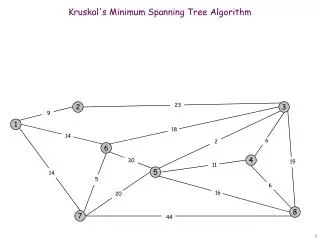
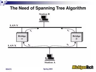
Spanning Tree Why a tree? If you have 2 switches that are connected in parallel, it could create a loop. LAN Connection A B Incoming broadcast frame
More Reasons Spanning Tree Disables one of these connections. It also keeps track of each of these connections. If the active connection becomes disconnected, it will reactivate it. How does it do this?
General Concepts • Bridges share information through Bridge Protocol Data Units or BPDUs. • Two important parameters that are passed in the BPDUs are the Bridge Identifier and the Root Identifier. • Each Identifier value is composed of a Bridge Priority and the Bridge MAC address. The Bridge Priority is settable in management so that Spanning Tree can be configured. • Upon Initialization all Bridges assume that they are root. The Bridge Identifier and the Root Identifier are thus equal upon initialization.
A B C D E F How does Spanning Tree Work? Root
Port States Bridge ports operate the Spanning Tree algorithm using the following states: Blocking - incoming frames are discarded. Listening - incoming frames are discarded, but the port is in the process of transitioning to Learning. Learning - incoming frames are discarded, but their source addresses and ports are placed in the Filtering Database. Forwarding - Incoming frames are forwarded, source addresses are learned. Disabled - The port is disabled by management.
Path Cost Varying networking technologies have a path cost associated with their speed.
Initialization Procedure • Used by all bridges on startup to make each bridge think that it is the root bridge. • Root ID set to Bridge ID for each bridge. • Root Path Cost set to zero for each bridge. • All Ports on each bridge become designated ports. • Configuration BPDU transmitted on each designated port on each bridge. • The Hello Timer is started for each bridge.
Transmit Configuration BPDU • If the Hold Timer is active we set the config_pending flag for the transmitting port. This Configuration BPDU will then be transmitted upon expiration of the Hold Timer for this Port. This ensures that no more than one Configuration BPDU is transmitted per Hold Time period. • Otherwise, we build a Configuration BPDU and if the Message Age for the BPDU we are about to transmit is less than Max Age, then we transmit the BPDU. • After transmission, the topology_change_acknowledge and config_pending flags held for the port are set to False, and the Hold Timer is started for the transmitting port.
Transmit Configuration BPDU • Protocol Identifier set to 0x0000 • Protocol Version Identifier and BPDU Type set to 0x00 • If the transmitting bridge is the root bridge, Message Age is set to zero, otherwise it is set to the value of the root port’s Message Age timer plus the Message_age_increment. • All other fields are set to the information stored for the transmitting port and bridge Protocol Identifier Protocol Version Identifier BPDU Type TCA Reserved TC Root Identifier Root Path Cost Bridge Identifier Port Identifier Message Age Max Age Hello Time Forward Delay
Receive Configuration BPDU • If the receiving port’s state is not Disabled: • If the information in the received BPDU supersedes the information currently stored for the receiving port: • Record the information from the BPDU. • Update the bridge and port configuration by selecting a root port and designated ports. • Select states for all ports on the receiving bridge. • If we were the root bridge prior to the configuration update but aren’t now: • stop the Hello Timer.
Receive Configuration BPDU • If the receiving bridge’s topology_change_detected flag is set: • Stop the topology_change_timer. • Transmit a Topology Change Notification BPDU. • Start the tcn_timer. • If the receiving port is the root port: • Record the timer values from the BPDU. • Transmit Configuration BPDUs on all the designated ports on the receiving bridge.
Receive Configuration BPDU If the received BPDU was a topology change acknowledgment: • Reset the topology_change_detected flag and stop the tcn_timer. • If the information received in the BPDU doesn’t supersede that stored for the receiving bridge and port but the receiving port is a designated port, generate a reply on the receiving port.
Supersedes Port Info • If the value of the Root Identifier, Root Path Cost, or Bridge Identifier fields received in the Configuration BPDU is less than the value stored for the receiving port for the designated_root, designated_cost, or designated_bridge parameter respectively, return True. • If the value of the Port Identifier field received in the Configuration BPDU is less than or equal to the designated port value stored for the receiving port, return True. • Otherwise, return False.
Record Configuration Info • Updates the designated_root, designated_cost, designated_bridge, and designated_port values stored for the receiving port to the Root Identifier, Root Path Cost, Bridge Identifier, and Port Identifier fields of the received Configuration BPDU, respectively. • Start the Message Age Timer with the initial timer value being the value contained in the Message Age field of the received Configuration BPDU.
Port State Selection • All ports on the bridge that are either a root port or a designated port are put into the forwarding state • All other ports are put into the blocking state
More on Learning Thus, address learning for the Filtering Database is dependent upon the state of Spanning Tree. When a bridge is alerted to a topology change, addresses are aged out according to the Spanning Tree Forward Delay time.
Make Forwarding • If the port we wish to make forwarding is currently in the blocking state, then set the port’s state to listening and start the forward delay timer for that port.
Make Blocking • If the current port state is not disabled or blocking • If the current port state is forwarding or learning • If the change_detection_enabled is set to True • Call Topology Change Detection • Set the port state to blocking • Stop the forward delay timer for that port
Topology Change Detection • If we are the root bridge • Set the bridge’s topology change flag to True • Start the topology change timer • Otherwise, if our topology_change_detected flag is currently set to false • Transmit a TCN BPDU • Start the tcn timer • Set the bridges’ topology_change_detected flag to True
A B C D E F G A Quick Example Root
Tick • This is the procedure that checks every clock tick to see whether any of the Spanning Tree Timers have expired. The timers involved are the hello_timer, tcn_timer, topology_change_timer, message_age_timer, forward_delay_timer, and the hold_timer.
Hello Timer Expiry • Call config_bpdu_generation for this bridge • Restart the hello timer for this bridge
Message Age Timer Expiry • Call the become_designated_port procedure for this port • Call the configuration_update procedure • Call the port_state_selection procedure • If we are the root bridge now but weren’t before the message age timer expired • Update the max_age, hello_time, and forward_delay parameters to those stored on this bridge • Call topology_change_detection • Stop the tcn_timer
Message Age Timer Expiry • Call the config_bpdu_generation procedure • Start the hello timer for this bridge
Forward Delay Timer Expiry • If the current port state is Listening • Set the port state to learning • Restart the forward_delay_timer for the port • Otherwise, if the current port state is Learning • Set the port state to forwarding • If this bridge has at least one designated port on it • If the change_detection_enabled flag is set to True • Call topology_change_detection
TCN Timer Expiry • Transmit a TCN BPDU • Restart the tcn_timer
Topology Change Timer Expiry • Set the topology_change_detected flag for the bridge to False • Set the topology_change flag for the bridge to False
Hold Timer Expiry • If the config_pending flag for the port is set • Transmit a Configuration BPDU on that port
Initial Bridge Parameters: Bridge Priority Path Cost B1 1 20 B2 2 15 B3 2 25 - All Ports on each bridge have the same Path Cost in this example. - The Max Age, Hello Time, and Forward Delay parameters are left at their default values of 20.0, 2.0, and 15.0 respectively.
Initial Bridged LAN Topology LAN A B1 0 LAN B B2 B3 15 25 LAN C
Active Bridged LAN Topology after Bootup LAN A B1 0 LAN B B2 B3 15 25 LAN C
Initial Bridge Parameters: Bridge Priority Path Cost B1 1 20 B2 2 15 B3 2 25 B4 2 15 - All Ports on each bridge have the same Path Cost in this example. - The Max Age, Hello Time, and Forward Delay parameters are left at their default values of 20.0, 2.0, and 15.0 respectively.
Adding An Additional Bridge to an Active Spanning Tree Topology LAN A B1 0 LAN B B2 New B4 B3 15 25 40 30 LAN C
Active Bridged LAN Topology after Spanning Tree Reconfiguration LAN A B1 0 LAN B B2 New B4 B3 15 25 30 LAN C