Download
1 / 24
240 likes | 379 Vues
EBW Coupling at 8-40 GHz for L- and H-Mode Plasmas. Steffi Diem Wave-Particle ET Meeting Jan. 23 rd , 2007. Goal for 2007: Understanding EBE in L- and H-Mode Plasmas. Study H- & L-mode coupling physics with improved diagnostics

E N D
EBW Coupling at 8-40 GHz for L- and H-Mode Plasmas Steffi Diem Wave-Particle ET Meeting Jan. 23rd, 2007
Goal for 2007: Understanding EBE in L- and H-Mode Plasmas • Study H- & L-mode coupling physics with improved diagnostics • Investigate variation of EBW coupling on plasma shape, Ip, z, etc. • Compare to EBE simulation with kinetic model EBW collisional damping • Outline- • Diagnostic overview • L-mode results and run plan • H-mode results and run plan
Remotely Steered EBW Antennas Allow Angular Mapping of fce & 2 fce B-X-O Coupling Window Beam waist • ±10° scan in poloidal and • toroidal directions • Acceptance angle: • 8-18 GHz antenna ~ 22° • 18-40 GHz antenna ~ 14° Ln~3 cm Ln~7 cm Antenna spatial scan region
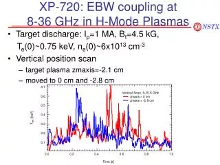
Strong fce Emission Observed During L-mode Scan • Target plasma Ip=0.8 MA, Te(0)~1.6 keV, ne~3x10¹³ m-3 • Discharge repeated to obtain B-X-O coupling map 120278
L-Mode B-X-O Emission Data from 2006 Run Agrees Well With Modeling at fce, but not 2fce • Measure ~70±20% fce(=15.5 GHz) coupling, but only ~25±10% 2fce coupling • EBW simulation predicts ~90% coupling at fce & 2fce f=25 GHz (2fce) f=15.5 GHz (fce) Possible causes: large Doppler broadening effects resulting in off-axis damping, EBW damping at conversion layer, problems with EBW simulation
Significant Disagreement Between Measured and Simulated Coupling for Most fce Frequencies • Measured coupling efficiency ~26% for fce=12 GHz; simulation predicts 60-80% • Similar observation made for fce<15.5 GHz • Possible causes - large Doppler broadening, collisional damping, problems with EBE code f=12 GHz (fce) Simulated Measured Trad Measured Simulated Trad uncertainty
Te(R) from 2006 EBE Data Disagrees with Thomson Scattering • Trad(R) profile for 120278, t=0.398s • Ray damping location obtained from EBE simulation code • Average Trad from EBE used in calculation • Bars show max. and min. damping location from 41-ray case Te (Thomson) Te (EBE sim.) fce 2fce
Three Main Objectives will Provide Further Understanding of B-X-O Coupling Physics • To investigate collisional effects on B-X-O mode coupling • Local gas puff injector installed in front of antennas • To investigate the effects of plasma parameters on B-X-O mode coupling • rtEFIT will be used to vary Ip, k, vertical position • To measure Te(R) using thermal EBW emission • Increase frequency range from 12-18 GHz to 8-18 GHz will provide more radial information
L-Mode Run Plan for 2007 Campaign • Modeling and data mining • Update B-X-O modeling code to include off-axis magnetic field information • Piggyback • Identify target discharge, Ip~0.8-1MA, Bt~0.4-0.55T • Run Plan (40 shots = 1.5 days) 5 - shot development 5(2) - gas puffs 2 - Li pellet injection shots 10(5) - parameter scans 3 - reflectometer shots 5 - low Ip ohmic shots
EBE Characteristics During H-Mode from 2006 Run Campaign • Burst emission • Decaying emission • H-mode with H-L back transition
2006 Scan of H-Mode Window Indicates Very Low Emission • Target discharge: Ip~1MA, Te(0)~0.9 keV, ne(0)~5e13 m-3 • Burst of emission observed shortly after L-H transition 120910
Very Low B-X-O Coupling Measured During H-mode Plasmas in 2006 • <10% coupling efficiency measured during Ip flattop (after emission burst) • Emission unpolarized after t~0.25s, indicating diagnostic measuring scattered emission H-Mode Possible causes: collisional damping, edge bootstrap current effects
Slowly Decaying EBE H-Mode Shot Observed • Discharge characteristics: Ip=1MA, Te(0)~1keV, ne(0)~4e1013 m-3 Shot 121227 t=0.3 s
Slowly Decaying EBE H-Mode Shot Observed (con't) • Emission slowly decays during discharge • Coupling efficiency drops from 40% to 15% • Antenna pointing direction not optimized • Similar to refraction effects observed on MAST • "Prospects of EBW Emission Diagnostics and EBW Heating in Spherical Tokamaks", V.F. Shevchenko, et. al. 121227 fce=15.5 GHz
Data Mining Suggests Reduced Emission May be Coupled to Z-Position • Emission burst occurs for z(0)>-0.2 m and decays when z(0)<-0.2 m • Possibly similar to results observed during EBW heating experiments on TCV 120910 121227 - decaying EBE 117970 - 30% [2005] 120910 - EBE burst
H-L Transition May Provide Insight to Understanding B-X-O Coupling in H-Modes • Discharge characteristics: Ip~750 kA, H-L transition at t~0.33s H-L 120217
H-L Transition May Provide Insight to Understanding B-X-O Coupling in H-Modes H-L • Event at t=0.35 s kills B-X-O emission For 2007 develop disruption-free discharge with H-L transition for bursting H-modes
Quiescent H-Mode from Previous Run Good Target Discharge • Fluctuation free edge • Steep edge gradients • Improve B-X-O coupling 117260
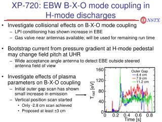
Low EBE During H-Mode will be Investigate During 2007 NSTX Run Campaign • Investigate collisional effects on B-X-O mode coupling • Li pellet injection will be used to modify edge Te and change collisionality at B-X-O mode conversion layer • Investigate effects of plasma parameters on B-X-O coupling • May help in understanding of B-X-O coupling physics • Bootstrap current from pressure gradient at H-mode pedestal may change field pitch at UHR: • Pitch may be large enough to move B-X-O emission window outside antenna acceptance angle • Install wide acceptance angle spiral antenna to detect EBE outside acceptance angle
H-Mode Run Plan 2007 Campaign • Modeling and data mining • Create database of H-mode emission and z(0) and other plasma parameters • Piggyback data • Look for stray emission using wide angle antenna • Identify either quiescent H-mode or bursting emission H-mode for current target plasma • Look for H-modes with high edge Te • Run plan (50 shots = 2 days) 10(5) - shot development for quiescent H-mode target plasma 5 - data shots for reflectometer and fast recipricating probe 5 - Li pellet injection to condition edge during discharge 5 - shot development for bursting emission H-mode discharge 5 - vary vertical position and other plasma parameters to increase emission 5(2) - introduce early H-L transition during Ip flattop 15 - plasma shaping scan to increase edge Te
120215 H-L t=0.42s t=0.3s