Download
1 / 21
210 likes | 346 Vues
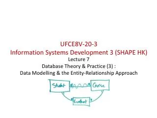
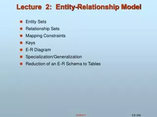
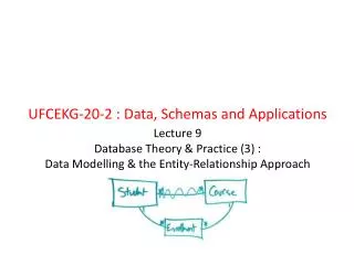
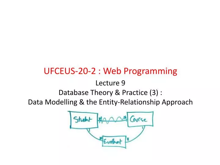
UFCEUS-20-2 : Web Programming. Lecture 9 Database Theory & Practice (3) : Data Modelling & the Entity-Relationship Approach. E-R modelling concepts (1).

E N D
UFCEUS-20-2 : Web Programming Lecture 9Database Theory & Practice (3) :Data Modelling & the Entity-Relationship Approach
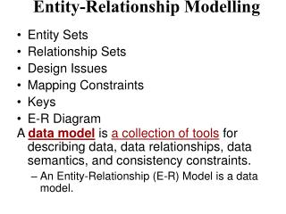
E-R modelling concepts (1) • Entity & AttributeAn entity is anything relevant to the Universe of Discourse (UoD) or domain. It can be defined as a group of logically associated data items identified by a unique key. ‘Entity type’ is used to describe all entities relevant to the domain which fit a given definition.
E-R modelling concepts (2) • Identifying entities This can be a difficult task. The analyst must gain a thorough understanding of the system environment. The entities could come to light, for example, from the dataflow diagrams produced during systems investigation. Another method is to find the things in the environment which need to be individually identified and referred to. Notional keys can be used to identify a range of other data - for example, a customer number identifies customer name and address, class, credit limit etc., which leads us to identify the CUSTOMER entity. Examples of notional keys could include: • Customer number • Product code • Job number • Account number.
E-R modelling concepts (3) • Attributes An attributeis a property or characteristic of an entity about which there is a need to record data; it is the named column of a relation. The attribute typeis the collection of all values of a defined property associated with a given entity type. Note: there is no absolute distinction between entity type and attribute type - an attribute type in one context can be an entity type in another. For example, to a car manufacturer, COLOUR is an attribute of the entity type CAR; to a paint manufacturer, COLOUR may well be an entity type.
E-R modelling concepts (4) • Null values A special value called the null value may be created when there is no value for an attribute. Null can be used for one of two reasons: either an entry is not applicable or it is not known. - An example of 'not applicable' would be the attribute Flat Number of an Address: this applies only to those people who live in flats; the Flat Number attribute would be null for those people who live in houses - An example of 'not known' would be the Height attribute of a Person being recorded as null if the height is unknown. When a table is implemented (using SQL), nulls are treated in a special way - as nulls rather than 'spaces' or zero. They are either displayed empty, or, if part of a calculated column, the whole record is excluded from the query, since it is not possible to determine the result of a calculation with null.
E-R modelling concepts (5) • Relationships A relationship is an association between entities that is operationally significant to the domain.
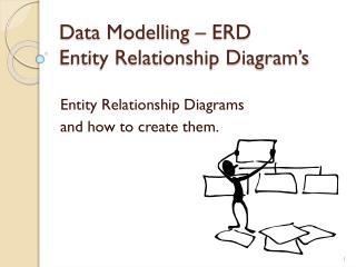
E-R modelling concepts (6) • The entity-relationship (E-R) diagram (an example)Entities and relationships can be used to produce a pictorial representation of the UoD. This picture is called an entity-relationship diagram. The figure on the next slide shows an entity-relationship diagram for the following scenario:“A University Library keeps information on books held, students who borrow these books and the loans which the students make. In addition, information is held about the authors and publishers of these books. A database designer has established the entities and attributes needed to carry out typical library functions and has produced the following entity-relationship diagram.”
E-R modelling concepts (7) An University Library System E-R diagram (using UML):
E-R modelling concepts (9) Notes on the diagram: • Note that the Book-Copy table holds information on the physical books stored in the library whereas the Book-Title table holds information on a particular publication of a book. • a book which is still out on loan will have a blank date-back field in the loan table • As copies of books become old, damaged and dirty, the books are removed from the library and destroyed. Destroyed book copies have a date to indicate this, otherwise the date is null. • The diagram also shows the maximum and minimum times that an entity occurrence can exist in a relationship. For example, a student can borrow zero or more books. This is called an optional relationship: occurrences of an entity (student) can exist independently of the loan entity. Otherwise, the relationship is mandatory: every occurrence of an entity participates in the relationship. In the book-title/authorship relationship, a title cannot exist without at least one author. The notation used will be explained more fully in the next section. An E-R diagram is drawn because: - By analysing the entities and relationships of an UoD, many hundreds of entities may be identified. The data model provides a concise summary of the results of the analysis - The E-R diagram will be used as the basis of database design. The structure of the model will be mapped onto the logical structure of the database.
E-R modelling concepts (8) E-R Diagramming Notation • Note that, traditionally, entity names are in the singular form • Rectangles are used to denote entity types (named normally as a noun) and lines represent relationship types • The lines are labelled with the names of the relationship (normally as a verb) • The arrow symbol indicates the correct direction for the name of the relationship to make sense. For example, a student makes many loan records. • The diagram (on the previous slide) uses a notation based on the unified modelling language (UML) for the entity-relationship diagram – there are a number of other notations also used (e.g. Chen, “crows-feet” notation).
E-R modelling concepts (10) Example - An E-R diagram of a Chess League (using the OMT notation):
E-R modelling concepts (10) Example - An E-R diagram using Chen’s notation:
E-R modelling concepts (10) Example - An E-R diagram using Crow’s Feet notation:
E-R modelling concepts (11) • The cardinality of a relationship There are several relationship types: • One-to-one relationships • One-to-many relationships • Many-to-many relationships • Recursive (or involute) relationships
E-R modelling concepts (12) • One-to-one relationshipIn a 1-to-1 relationship, an occurrence of the first entity type is related to a maximum of one occurrence of the second entity type, and each occurrence of the second type to a maximum of one of the first. One member of parliament is elected to one constituency; one constituency has one MP elected to it.
E-R modelling concepts (13) • One-to-many relationship In a 1-to-m relationship, an occurrence of the first entity type may be related to several occurrences of the second, but each occurrence of the second is related to a maximum of one occurrence of the first. Onecustomer places zero or more orders; one order is placed by one customer.
E-R modelling concepts (14) • Many-to-many relationship In a m-to-m relationship, an occurrence of the first entity type may be related to several occurrences of the second and vice versa. One depot holds zero or more products; one product is held at one or more depots.
E-R modelling concepts (15) • Recursive (or involute) relationship In a recursive relationship, entity occurrences relate to other occurrences of the same entity. Oneemployee (a manager) manages one to twenty employees; oneemployee is managed by one employee (manager).
E-R modelling concepts (16) • Decomposition All many-to-many relationships, can be decomposed into two one-to-many relationships. One reason for doing this is that relational DBMSs do not support many-to-many relationships directly. Also, by eliminating many-to-many relationships, problems in the model become easier to spot.
E-R modelling concepts (17) • Key attributes It may be necessary to specify one or more of the attributes of an entity as a 'key' of the entity. This is particularly true of the relational model. Three types of keys are defined here: • Acandidate key is a unique identifier for the entity - there may be more than one candidate key (for example, customer-no, customer address) • A primary key (PK) is also a unique identifier for the entity - that is, an attribute (or combination of attributes) with the property that, at any given time, no two entity occurrences contain the same values for that attribute (or combination of attributes). One candidate key is chosen as the primary key. (Between the two candidate keys mentioned above it is likely that customer-no would be chosen as the primary key as this is more likely to be unique.) • Aforeign key (FK)is an attribute in a relation which is also the primary key in another relation (often) or a candidate key (sometimes).
Bibliography / Readings / Home based activities Bibliography • An Introduction to Database Systems (8th ed.), C J Date, Addison Wesley 2004 • Database Management Systems, P Ward & G Defoulas, Thomson 2006 • Database Systems Concepts (4th ed.), A Silberschatz, H F Korth & S Sudarshan, McGraw-Hill 2002