Download
1 / 17
170 likes | 266 Vues
High precision image-based tracking of a rigid body moving within a fluid. Stuart Laurence, Jan Martinez Schramm German Aerospace Center (DLR), G öttingen, Germany APS/DFD, 23 November 2010. Motivation.

E N D
High precision image-based tracking of a rigid body moving within a fluid Stuart Laurence, Jan Martinez Schramm German Aerospace Center (DLR), Göttingen, Germany APS/DFD, 23 November 2010
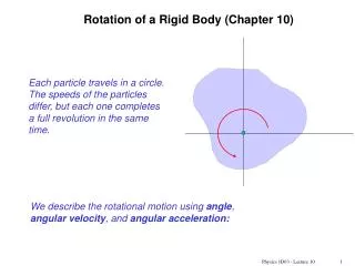
Motivation • Visualization-based techniques an attractive option for measuring displacements (and derived quantities) of rigid bodies in fluids, as they are completely non-intrusive • Particularly attractive for force-measurement in short-duration hypersonic facilities, as few other options available • However, measurement precision critical – in past (film-based analog techniques) displacement measurements limited to ~50 μm • Focus here on edge-detection-based techniques combined with least-squares fitting (suitable for silhouette images from schlieren, etc.) • Assumptions: no changes to body profile; motion two dimensional + one axis of rotation
Analytic-fitting technique Edge detection Model edge tracing and sub-pixel detection Least-squares fitting
Free-flight measurements with analytic-fitting technique • Image-based measurements show reasonable agreement with accelerometer measurements • Response time for 14 kfps estimated to be ~0.5 ms
Problems with analytic-fitting technique • Model cross-sectional profile must be expressible analytically (can be avoided by using, e.g., splines) • For all but simplest geometries, fitting procedure is iterative (slow!) • Reasonably complete profile required for convergence
Edge-tracking technique • Based on matching closest edge-points in reference and displaced images • Edge angle assumed to be the same for each edge-point pair
Edge-tracking technique • Based on matching closest edge-points in reference and displaced images • Edge angle assumed to be the same for each edge-point pair linear least-squares problem for Δx and Δy b) with errors a) no errors
Error estimation through artificial image analysis • Errors introduced by pixellation/edge-detection (can be reduced through more precise algorithms) and CCD noise (unavoidable at given light conditions) • Such errors can be estimated through analysis of artificially constructed images
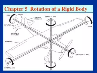
Error determination from calibrated sphere measurements • Precision-machined 40-mm diameter sphere controlled by linear displacement stepper • Magnification ~300 μm/pixel • Position determination from tracking techniques compared with inputted displacements • Standard error ~1.3 μm (A) Shimadzu HPV-1; (B) Telephoto lens; (C) Precision-machined sphere; (D) Linear displacement stage; (E) Light source; (F) Light-diffusing material
Errors in constant acceleration measurements • Error in measured constant acceleration, a, can be determined from assumed displacement error (δ): (n = number of measurement points) • For micron-level precision in displacement, accurate (~1%) acceleration measurements possible even for millisecond test times
Errors in constant acceleration measurements • Error in measured constant acceleration, a, can be determined from assumed displacement error (δ): (n = number of measurement points) • For micron-level precision in displacement, accurate (~1%) acceleration measurements possible even for millisecond test times
Conclusions • Technique originally developed for bodies with analytically expressible cross-sections • Generalized to arbitrary body geometries • Displacement measurements to micron level for wind-tunnel scale models – allows acceleration measurements to <1% under typical conditions • Generalization to three-dimensional motions?
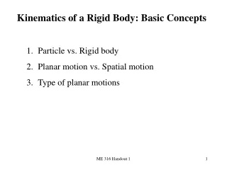
Shock-wave surfing Error in edge-point locations Optical distortions can become problematic for large fields-of-view Can be corrected for using reference images
Shock-wave surfing Displacements Optical distortions can become problematic for large fields-of-view Can be corrected for using reference images
Shock-wave surfing Force coefficients Optical distortions can become problematic for large fields-of-view Can be corrected for using reference images