Download
1 / 36
360 likes | 365 Vues
ION ITM 2011 San Diego, CA Jan. 24-26, 2011. QZSS L1-SAIF Initial Experiment Results. T. Sakai, S. Fukushima, and K. Ito Electronic Navigation Research Institute, Japan. Introduction. QZSS (Quasi-Zenith Satellite System) program :

E N D
ION ITM 2011 San Diego, CA Jan. 24-26, 2011 QZSS L1-SAIF Initial Experiment Results T. Sakai, S. Fukushima, and K. Ito Electronic Navigation Research Institute, Japan
Introduction • QZSS (Quasi-Zenith Satellite System) program: • Regional navigation service broadcast from high-elevation angle by three satellites on the inclined geosynchronous (quasi-zenith) orbit; • Broadcast GPS-compatible supplemental signals on three frequencies and two augmentation signals, L1-SAIF and LEX; • The first QZS satellite successfully launched on Sept. 11, 2010. • L1-SAIF (Submeter-class Augmentation with Integrity Function) signal offers: • Sub-meter accuracy wide-area differential correction service; • Integrity function for safety of mobile users; and • Ranging function for position availability; all on L1 single frequency. • ENRI has been developing L1-SAIF signal and experimental facility: • Signal design: SBAS-compatible on L1; • Implemented L1-SAIF Master Station (L1SMS) which generates augmentation message stream in realtime and transmits it to QZSS MCS; • Now conducting experiments on L1-SAIF.
Part 1 Overview of QZSS Program
Launch of QZS-1 “Michibiki” Sept. 11, 2010 20:17JST Launch of QZS-1 “Michibiki” • Launched by H-IIA-18 from Tanegashima Space Center of JAXA; • “Michibiki” was separated successfully 28:27 after launch. Michibiki looked from the second stage (c) JAXA/MHI (c) MHI
QZSS Concept QZS GPS/GEO • Broadcast signal from high elevation angle; • Applicable to navigation services for mountain area and urban canyon; • Augmentation signal from the zenith could help users to acquire other GPS satellites all the time. • Footprint of QZS orbit; • Centered 137E; • Eccentricity 0.1, Inclination 45deg.
QZSS Program • QZSS (Quasi-Zenith Satellite System) program: • Japan has been developing QZSS since FY 2003; • Regional navigation service broadcast from high-elevation angle by combination of three satellites on the inclined geosynchronous (quasi-zenith) orbit; • Broadcast GPS-compatible supplemental signals on three frequencies (L1 C/A, L1C, L2C, and L5) and two augmentation signals, L1-SAIF and LEX. • Participating institutes: • JAXA (Japan Aerospace Exploration Agency): Development and operation of the space segment and Master Control Station; • NICT (National Institute of Information and Communication Technology): Frequency standard and time keeping system including Uplink Station; • AIST (National Institute of Advanced Industrial Science and Technology): Time synch-ronization between space and ground; • GSI (Geographical Survey Institute): Survey-grade carrier-based positioning service; • ENRI (Electronic Navigation Research Institute): Navigation-grade WADGPS service broadcast by L1-SAIF signal.
GPS Satellites Navigation Signals L1: 1575.42 MHz L2: 1227.60 MHz L5: 1176.45 MHz LEX: 1278.75 MHz QZS Satellite TWSTFT Up: 4.43453GHz Down: 12.30669GHz Satellite Laser Ranging TT&C / NAV Message Uplink TT&C / NAV Msg Uplink Station Time Mgmt Station Monitor Station NW SLR Site User Receiver Master Control Station (MCS) GEONET (GSI) Function distributed in each institute Timing management by NICT, WADGPS service by ENRI, etc. TWSTFT: Two Way Satellite Time and Frequency Transfer (Courtesy: JAXA QZSS PT) Overall Architecture
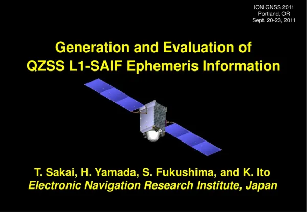
25.3m Radiation Cooled TWT TWSTFT Antenna C-band TTC Antenna Laser Reflector L1-SAIF Antenna L-band Helical Array Antenna Space Segment: QZS-1
QZSS Signals • Supplemental signals: • GPS-compatible L1C/A, L2C, L5, and L1C signals working with GPS; improving availability of navigation; • With minimum modifications from GPS signal specifications; • Coordination with GPS Wing on broadcasting L1C signal; • JAXA is responsible for all supplemental signals. • Augmentation signals: • Augmentation to GPS; Possibly plus Galileo; • L1-SAIF: Compatible with SBAS; reasonable performance for mobile users; • LEX: For carrier-based experimental purposes; member organizations may use as 2kbps experimental data channel; • ENRI is working for L1-SAIF while JAXA is developing LEX. • Interface Specification: IS-QZSS available on JAXA HP • Specifies RF signal interface between QZS satellite and user receiver; • First issue: Jan. 2007; Maintained by JAXA.
QZSS Frequency Plan Signal Channel Frequency Bandwidth Min. Rx Power QZS-L1C L1CD 1575.42 MHz 24 MHz –163.0 dBW L1CP 24 MHz – 158.25 dBW QZS-L1-C/A 24 MHz – 158.5 dBW QZS-L1-SAIF 24 MHz – 161.0 dBW QZS-L2C 1227.6 MHz 24 MHz – 160.0 dBW QZS-L5 L5I 1176.45 MHz 25 MHz – 157.9 dBW L5Q 25 MHz – 157.9 dBW QZS-LEX 1278.75 MHz 42 MHz – 155.7 dBW Find detail in IS-QZSS document.
Part 2 L1-SAIF Signal Design
QZSS L1-SAIF Signal • QZSS will broadcast wide-area augmentation signal: • Called L1-SAIF (Submeter-class Augmentation with Integrity Function); • Developed by ENRI. • L1-SAIF signal offers: • Wide-area differential correction service for improving position accuracy; Target accuracy: 1 meter for horizontal; • Integrity function for safety of mobile users; and • Ranging function for position availability. • Interoperable with GPS L1C/A and fully compatible with SBAS: • Broadcast on L1 freq. with RHCP; Common antenna and RF front-end; • Modulated by BPSK with C/A code; • 250 bps data rate with 1/2 FEC; message structure is identical with SBAS; • Differences: Large Doppler and additional messages; • Specification of L1-SAIF: IS-QZSS document.
Ranging Function QZS satellite GPS Constellation Error Correction Ranging Signal Integrity Function L1-SAIF Signal • Three functions by a single signal: ranging, error correction (Target accuracy: 1m), and integrity; • User receivers can receive both GPS and L1-SAIF signals by a single antenna; • Message-oriented information transmission: flexible contents. User GPS Receivers SAIF: Submeter-class Augmentation with Integrity Function
Clock Correction • Same contribution to any user location; • Not a function of location; • Needs fast correction. Ionospheric Correction • Function of user location; • Up to 100 meters; • Vertical structure may be described as a thin shell. Orbit Correction • Different contribution to different user location; • Not a function of user location; but a function of line-of-sight direction; • Long-term correction. Ionosphere Tropospheric Correction • Function of user location, especially height of user; • Up to 20 meters; • Can be corrected enough by a fixed model. Troposphere WADGPS Concept
SBAS/L1-SAIF Message Structure Preamble 8 bits Message Type 6 bits Data Field 212 bits CRC parity 24 bits 250 bits per second Transmitted First MT Contents Interval [s] MT Contents Interval [s] 0 Test mode 6 17 GEO almanac 300 1 PRN mask 120 18 IGP mask 300 2~5 Fast correction & UDRE 60 24 FC & LTC 6 6 UDRE 6 25 Long-term correction 120 7 Degradation factor for FC 120 26 Ionospheric delay & GIVE 300 9 GEO ephemeris 120 27 SBAS service message 300 10 Degradation parameter 120 28 Clock-ephemeris covariance 120 12 SBAS time information 300 63 Null message — Note: Some additional messages are also defined for L1-SAIF. See IS-QZSS.
GPS/L1-SAIF Simulator GPS/L1-SAIF Receiver GPS/L1-SAIF Simulator • GPS/L1-SAIF Simulator: • Simulates GPS L1 C/A and QZSS L1-SAIF signals; • Generates RF signals based on pre-defined GPS and QZSS constellation scenario and signal specifications • of IS-GPS and IS-QZSS; • Manufactured by Spirent, modifying • GPS/SBAS simulator GSS7700. • Special function for experiment: • Added extra command to input • L1-SAIF message from Ethernet • port (TCP/IP); • L1-SAIF message is either input • by the command externally or • generated by the simulator internally.
GPS/L1-SAIF Receiver GPS/L1-SAIF Receiver • Prototype GPS/L1-SAIF Receiver: • Receives GPS L1 C/A and QZSS L1-SAIF signals; • Decode and apply L1-SAIF message as defined by IS-QZSS; • Manufactured by Furuno Electric. • Special function for experiment: • L1-SAIF message can be input from • Ethernet port (TCP/IP)as well as • L1-SAIF signal on RF; • Enable to process L1-SAIF and SBAS, • totally three, augmentation signals • simultaneously; • Portable equipage for experiment • at remote or on mobile.
ENRI (Chofu, Tokyo) Spirent Furuno Electric L1-SAIF Signal GPS/L1-SAIF Simulator RF Cable GPS/L1-SAIF Receiver File Scenario TCP/IP L1-SAIF Message Decoded Message Compare RF Compatibility Test • Ranging function: The receiver output the proper position solution with pseudorange of L1-SAIF signal generated by the simulator; • Decoding message: The receiver decoded L1-SAIF message which matched with the message input to the simulator via Ethernet port; The command needs to be given 2-second before the applicable time of transmission; • Successfully completed in Feb. 2009.
RF Compatibility Test 2008/9/10 00:05:00 to 06:00:00 (6 hours) Standalone GPS L1-SAIF Augmentation OK!
Part 3 L1-SAIF Master Station (L1SMS)
QZS GPS L1C/A, L2P L1-SAIF Signal K-band L1C/A, L2P Closed Loop Measured Data L1-SAIF Message GEONET L1SMS QZSS MCS GSI ENRI JAXA ENRI L1SMS • L1-SAIF Master Station (L1SMS): • Generates L1-SAIF message stream in realtime and transmits it to QZSS MCS developed by and installed at JAXA; • Installed at ENRI, Tokyo; 90km from JAXA Tsukuba Space Center; • Subsystems: GEONET Server, Primary Receiver, Interface Processor, Message Generator, Ionosphere Processor, Troposphere Processor, and Batch Processor.
Message Generator Ionosphere Processor I/F Storage Storage Storage Router to GEONET GEONET Server UPS UPS L1SMS Installed at ENRI
GEONET TCP/IP Dual Freq. ANT Observation File (RINEX) via FTP Message Output via TCP/IP GEONET Server Primary Receiver Batch Processor (IFB Estimation) Interface Processor IFB Estimates Ionosphere Processor Troposphere Processor Message Generator (L1SMG) L1SMS Batch Subsystem L1SMS Realtime Subsystems Configuration of L1SMS
Standalone GPS L1-SAIF Augmentation System Horizontal Error Vertical Error Standalone GPS RMS 1.45 m 2.92 m Max 6.02 m 8.45 m L1-SAIF RMS 0.29 m 0.39 m Max 1.56 m 2.57 m Position Error Sample • Example of user position error at Site 940058 (Takayama; near center of monitor station network); • Realtime operation with MSAS-like 6 monitor stations; • Period: 19-23 Jan. 2008 (5 days). Note: Results shown here were obtained with geodetic-grade antenna and receivers at open sky condition.
Realtime Operation using GEO GPS Satellites ETS-VIII Satellite L1-SAIF L1SMS in Tokyo GPS/L1-SAIF Rx in Sendai Airport 350 km Separation • ENRI joined communication experiment of ETS-VIII geostationary satellite; • L1SMS transmitted L1-SAIF message to ETS-VIII; Received L1-SAIF message was input to the GPS/L1-SAIF receiver and processed in realtime; No ranging function; • Successfully completed in Feb. 2009.
L1-SAIF Receiver Output 2009/2/17 01:21:39 to 07:23:14 (6 hours) Standalone GPS L1-SAIF Augmentation H Error RMS = 1.221m V Error RMS = 4.043m H Error RMS = 0.412m V Error RMS = 0.464m
Part 4 Experiment with QZS-1 “Michibiki”
Reception of Test Signal • Firstly received L1-SAIF test signal broadcast from QZS on orbit; • By L1-SAIF prototype receiver on Oct. 23, 2010 09:46:48-10:48:07GPST at a branch of ENRI in Sendai Airport, Located at the Northern part of Japan; • Raw pseudorange: receiver clock variation is dominant and there are jumps due to clock adjustment.
Experiment by Car GPS+IMU • L1-SAIF experiment: • L1-SAIF is originally planned as an augmentation to mobile users with a certain velocity; • Experiment with a car; • Location: urban/suburban environment, freeway; • Experiment period: Dec. 2010 to March 2011. • Experiment setup: • Reference: GPS+IMU sensor; • Post-processing with GEONET stations (20- 30 km separation) for accurate reference; • GPS/L1-SAIF receiver and PC in cabin; • Receives L1-SAIF signal on PRN 183; • Applies L1-SAIF corrections in realtime and outputs position fix. GPS/L1-SAIF Rx
GEONET Ichinomiya 2 km GEONET Nakamichi On the Freeway Plan View of the Route Typical Situation • On Dec. 14, 2010; QZS near the Zenith; • About 10 km drive at the Kofu Basin on Chuo Freeway going westward from Tokyo; • Plain ground with less bridges across the Freeway.
Freeway: L1-SAIF Augmented Chuo Freeway: L1-SAIF Augmentation Horizontal Position Error, m 0.5m UTC Time 1:22:08 to 1:37:08 15min
Freeway: GPS No Augmentation Chuo Freeway: GPS without Augmentation Horizontal Position Error, m 1.2m UTC Time 1:22:08 to 1:37:08 15min
GEONET Tsukuba 1 1 km In Tsukuba City Plan View of the Route Typical Situation • On Dec. 16, 2010; QZS near the Zenith; • About 6 km drive in West part of Tsukuba City in Ibaraki Pref.; • Road on the ground level with less tall buildings around.
Tsukuba: L1-SAIF Augmented Tsukuba: L1-SAIF Augmentation Horizontal Position Error, m 0.6m UTC Time 5:30:01 to 5:45:01 15min
Tsukuba: GPS No Augmentation Tsukuba: GPS without Augmentation Horizontal Position Error, m 2.0m UTC Time 5:30:01 to 5:45:01 15min
Conclusion • ENRI has been developing L1-SAIF signal: • Signal design: GPS/SBAS-compatible; • Planned as an augmentation to mobile users; • Implemented L1-SAIF Master Station (L1SMS) which generates augmentation message stream in realtime and transmit it to QZSS MCS. • QZSS satellite “Michibiki”: • The first satellite for QZSS, “Michibiki”, was successfully launched; • Successfully passed initial function tests for Bus and Mission by end Nov.; • Currently in the nominal operation status. • Ongoing work: • Now L1-SAIF experiment has been conducted by ENRI; • Preliminary results show accuracy improvement by L1-SAIF augmentation.