Download
1 / 58
640 likes | 957 Vues
Pump Basics. Pump. A pump is a device that moves fluids (liquids or gases), or sometimes slurries, by mechanical action. Centrifugal Pumps. A machine for moving fluid by accelerating the fluid RADIALLY outward. From the Center of a Circle. RADIAL DIRECTION To the Outside of a Circle.

E N D
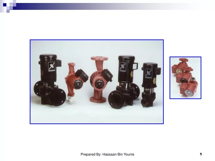
Pump Basics Prepared By: Hassaan Bin Younis
Pump A pump is a device that moves fluids (liquids or gases), or sometimes slurries, by mechanical action. Prepared By: Hassaan Bin Younis
Centrifugal Pumps A machine for moving fluid by accelerating the fluid RADIALLY outward. From the Center of a Circle RADIAL DIRECTION To the Outside of a Circle Prepared By: Hassaan Bin Younis
Centrifugal Pumps • This machine consists of an IMPELLER rotating within a case (diffuser) • Liquid directed into the center of the rotating impeller is picked up by the impeller’s vanes and accelerated to a higher velocity by the rotation of the impeller and discharged by centrifugal force into the case (diffuser). Prepared By: Hassaan Bin Younis
Centrifugal Pumps • A collection chamber in the casing converts much of the Kinetic Energy (energy due to velocity) into Head or Pressure. Prepared By: Hassaan Bin Younis
Pump Terminology Prepared By: Hassaan Bin Younis
Pressure Gauge "Head" • Head is a term for expressing feet of water column • Head can also be converted to pressure Reservoir of Fluid 100 feet 43.3 PSI Prepared By: Hassaan Bin Younis
Conversion Factors Between Head and Pressure • Head (feet of liquid) =Pressure in PSI x 2.31 / Sp. Gr. • Pressure in PSI = Head (in feet) x Sp. Gr. / 2.31 • PSI is Pounds per Square Inch • Sp. Gr. is Specific Gravity which for water is equal to 1 • For a fluid more dense than water, Sp. Gr. is greater than 1 • For a fluid less dense than water, Sp. Gr. is less than 1 Prepared By: Hassaan Bin Younis
Head • Head and pressure are interchangeable terms provided that they are expressed in their correct units. • The conversion of all pressure terms into units of equivalent head simplifies most pump calculations. Prepared By: Hassaan Bin Younis
Impeller Vanes “Eye of the Impeller” Water Entrance Thickness of the impeller Diameterof the Impeller Centrifugal Impellers • Thicker the Impeller- More Water • Larger the DIAMETER - More Pressure • Increase the Speed - More Water and Pressure Prepared By: Hassaan Bin Younis
Two Impellers in Series • Twice the pressure • Same amount of water Direction of Flow Prepared By: Hassaan Bin Younis
Multiple Impellers in Series • Placing impellers in series increases the amount of head produced • The head produced = # of impellers x head of one impeller Direction of Flow Direction of Flow Prepared By: Hassaan Bin Younis
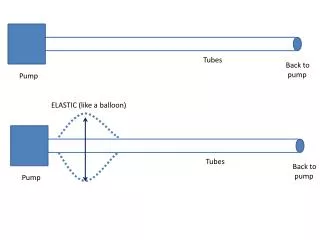
Reciprocating pump Pumps are used to increase the energy level of water by virtue of which it can be raised to a higher level. Reciprocating pumps are positive displacement pump, i.e. initially, a small quantity of liquid is taken into a chamber and is physically displaced and forced out with pressure by a moving mechanical elements. The use of reciprocating pumps is being limited these days and being replaced by centrifugal pumps. Prepared By: Hassaan Bin Younis
Reciprocating pump For industrial purposes, they have become obsolete due to their high initial and maintenance costs as compared to centrifugal pumps. Small hand operated pumps are still in use that include well pumps, etc. These are also useful where high heads are required with small discharge, as oil drilling operations. Prepared By: Hassaan Bin Younis
Main components A reciprocation pumps consists of a plunger or a piston that moves forward and backward inside a cylinder with the help of a connecting rod and a crank. The crank is rotated by an external source of power. The cylinder is connected to the sump by a suction pipe and to the delivery tank by a delivery pipe. At the cylinder ends of these pipes, non-return valves are provided. A non-return valve allows the liquid to pass in only one direction. Through suction valve, liquid can only be admitted into the cylinder and through the delivery valve, liquid can only be discharged into the delivery pipe. Prepared By: Hassaan Bin Younis
Main components Prepared By: Hassaan Bin Younis
Working of Reciprocating Pump When the piston moves from the left to the right, a suction pressure is produced in the cylinder. If the pump is started for the first time or after a long period, air from the suction pipe is sucked during the suction stroke, while the delivery valve is closed. Liquid rises into the suction pipe by a small height due to atmospheric pressure on the sump liquid. During the delivery stroke, air in the cylinder is pushed out into the delivery pipe by the thrust of the piston, while the suction valve is closed. When all the air from the suction pipe has been exhausted, the liquid from the sump is able to rise and enter the cylinder. Prepared By: Hassaan Bin Younis
Working of Reciprocating Pump • During the delivery stroke it is displaced into the delivery pipe. Thus the liquid is delivered into the delivery tank intermittently, i.e. during the delivery stroke only. Prepared By: Hassaan Bin Younis
Classification of Reciprocating Pumps Following are the main types of reciprocating pumps: • According to use of piston sides • Single acting Reciprocating Pump: If there is only one suction and one delivery pipe and the liquid is filled only on one side of the piston, it is called a single-acting reciprocating pump. • Double acting Reciprocating Pump: A double-acting reciprocating pump has two suction and two delivery pipes, Liquid is receiving on both sides of the piston in the cylinder and is delivered into the respective delivery pipes. Prepared By: Hassaan Bin Younis
Classification of Reciprocating Pumps Prepared By: Hassaan Bin Younis
Classification of Reciprocating Pumps According to number of cylinder Reciprocating pumps having more than one cylinder are called multi-cylinder reciprocating pumps. • Single cylinder pump A single-cylinder pump can be either single or double acting • Double cylinder pump (or two throw pump) A double cylinder or two throw pump consist of two cylinders connected to the same shaft. Prepared By: Hassaan Bin Younis
Classification of Reciprocating Pumps According to number of cylinder • Triple cylinder pump (three throw pump) A triple-cylinder pump or three throw pump has three cylinders, the cranks of which are set at 1200 to one another. Each cylinder is provided with its own suction pipe delivery pipe and piston. • There can be four-cylinder and five cylinder pumps also, the cranks of which are arranged accordingly. Prepared By: Hassaan Bin Younis
Classification of Reciprocating Pumps Prepared By: Hassaan Bin Younis According to number of cylinder
Discharge through a Reciprocating Pump Let A = cross sectional area of cylinder r = crank radius N = rpm of the crank L = stroke length (2r) Discharge through pump per second= Area x stroke length x rpm/60 This will be the discharge when the pump is single acting. Prepared By: Hassaan Bin Younis
Discharge through a Reciprocating Pump Prepared By: Hassaan Bin Younis
Discharge through a Reciprocating Pump Discharge in case of double acting pump Discharge/Second = Where, Ap= Area of cross-section of piston rod However, if area of the piston rod is neglected Discharge/Second = Prepared By: Hassaan Bin Younis
Discharge through a Reciprocating Pump Thus discharge of a double-acting reciprocating pump is twice than that of a single-acting pump. Owing to leakage losses and time delay in closing the valves, actual discharge Qausually lesser than the theoretical discharge Qth. Prepared By: Hassaan Bin Younis
Slip of Pump Slip of a reciprocating pump is defined as the difference between the theoretical and the actual discharge. i.e. Slip = Theoretical discharge - Actual discharge = Qth. - Qa Slip can also be expressed in terms of %age and given by Prepared By: Hassaan Bin Younis
Slip of Pump Slip Where Cd is known as co-efficient of discharge and is defined as the ratio of the actual discharge to the theoretical discharge. Cd = Qa / Qth. Value of Cd when expressed in percentage is known as volumetric efficiency of the pump. Its value ranges between 95---98 %. Percentage slip is of the order of 2% for pumps in good conditions. Prepared By: Hassaan Bin Younis
Negative Slip It is not always that the actual discharge is lesser than the theoretical discharge. In case of a reciprocating pump with long suction pipe, short delivery pipe and running at high speed, inertia force in the suction pipe becomes large as compared to the pressure force on the outside of delivery valve. This opens the delivery valve even before the piston has completed its suction stroke. Thus some of the water is pushed into the delivery pipe before the delivery stroke is actually commenced. This way the actual discharge becomes more than the theoretical discharge. Thus co-efficient of discharge increases from one and the slip becomes negative. Prepared By: Hassaan Bin Younis
Reciprocating Pumps Problem:A single-acting reciprocating pump discharge 0.018 m3 /s of water per second when running at 60 rpm. Stroke length is 50 cm and the diameter of the piston is 22 cm. If the total lift is 15 m, determine: a) Theoretical discharge of the pumpb) Slip and percentage slip of the pumpc) Co-efficient of discharge Prepared By: Hassaan Bin Younis
Solution: (a) Qth = (π/4)x(0.22)2x(0.5x60/60) Qth = 0.019 m3 /s (b)Slip = Qth - Qa Slip = 0.019 – 0.018 = 0.001m3 /s Percentage slip = (Qth - Qa)/ Qth = (0.019-0.018)/0.019 = 0.0526 or 5.26% (c) Cd = Qa / Qth = 0.018/0.019 = 0.947 Prepared By: Hassaan Bin Younis
Comparison Prepared By: Hassaan Bin Younis
Pump Performance Curve • A mapping or graphing of the pump's ability to produce head and flow Prepared By: Hassaan Bin Younis
Pump Performance CurveStep #1, Horizontal Axis • The pump's flow rate is plotted on the horizontal axis ( X axis) • Usually expressed in Gallons per Minute Pump Flow Rate Prepared By: Hassaan Bin Younis
Pump Performance CurveStep #2, Vertical Axis • The head the pump produces is plotted on the vertical axis (Y axis) • Usually express in Feet of Water Head Pump Flow Rate Prepared By: Hassaan Bin Younis
Performance Curve Head Pump Performance CurveStep #3, Mapping the Flow and the Head • Most pump performance curves slope from left to right Pump Flow Rate Prepared By: Hassaan Bin Younis
Shut-off Head Head Pump Performance CurveImportant Points • Shut-off Head is the maximum pressure or head the pump can produce • No flow is produced Pump Flow Rate Prepared By: Hassaan Bin Younis
Maximum Flow Head Pump Performance CurveImportant Points • Maximum Flow is the largest flow the pump can produce • No Head is produced Pump Flow Rate Prepared By: Hassaan Bin Younis
System Performance Curves • System Performance Curve is a mapping of the head required to produce flow in a given system • A system includes all the pipe, fittings and devices the fluid must flow through, and represents the friction loss the fluid experiences Prepared By: Hassaan Bin Younis
System Performance CurveStep #1, Horizontal Axis • The System's flow rate in plotted on the horizontal axis ( X axis) • Usually expressed in Gallons per Minute System Flow Rate Prepared By: Hassaan Bin Younis
System Performance CurveStep #2, Vertical Axis • The head the system requires is plotted on the vertical axis (Y axis) • Usually express in Feet of Water Head Pump Flow Rate Prepared By: Hassaan Bin Younis
Head System Performance CurveStep #3, Curve Mapping • The friction loss is mapped onto the graph • The amount of friction loss varies with flow through the system Friction Loss Pump Flow Rate Prepared By: Hassaan Bin Younis
Head The point on the system curve that intersects the pump curve is known as the operating point. Pump Flow Rate Prepared By: Hassaan Bin Younis
Head PUMP SELECTION Circulator 1 Circulator 2 Circulator 3 Pump Flow Rate Prepared By: Hassaan Bin Younis
Controlling Pump Performance • Changing the amount for friction loss or "Throttling the Pump" will change the pump's performance Prepared By: Hassaan Bin Younis
Head PUMP SELECTION Valve Barely Open Valve Partially Open Valve Open Pump Flow Rate Prepared By: Hassaan Bin Younis