Download
1 / 37
460 likes | 915 Vues
Spread Spectrum Modulation. Dr. Teerasit Kasetkasem. Introduction. Introduction. Introduction. Introduction. Introduction. Concept of Spread-spectrum modulation It will spread the spectrum of transmitted signals into wider range.

E N D
Spread Spectrum Modulation Dr. Teerasit Kasetkasem
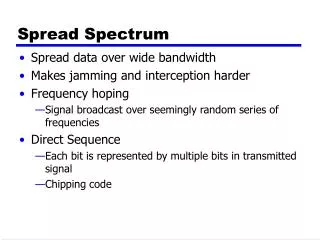
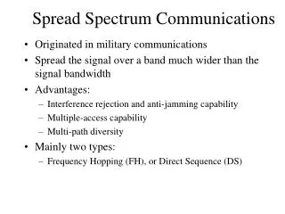
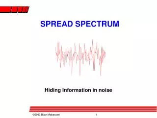
Introduction • Concept of Spread-spectrum modulation • It will spread the spectrum of transmitted signals into wider range. • The code is used to spread the spectrum of transmitted signals • Since the spectrum of transmitted signal is wider than its usual forms, spread spectrum modulation makes the signal very robust to unintentional interference or jamming.
Introduction • Types of Spread-Spectrum Modulations • Direct sequence spread spectrum: This means that transmitted signal is represented by a wideband code. This code transforms narrow band data into a noiselike wideband data. • Frequency-hop spread spectrum: Transmitted signal keeps randomly changing its carrier frequency in wideband range
Pseudo-Noise Sequences • Both types of spread-spectrum require a noiselike code which will be used to modulate with transmitted signal or control oscillator for direct sequence and frequency hopping, respectively. • This noiselike sequence is called pseudo-noise sequence or PN code.
Pseudo-Noise Sequences • Feedback shift registers are used.
Pseudo-Noise Sequences • Output sequence depends on the length of shift-register (m), initial state and feedback logic. • For m flip-flop the number of states is 2m. • The maximum length of the period of this sequence is also 2m.
Pseudo-Noise Sequences • In case that feedback logic consists entirely with modular-2 adders (XOR gate) only, the initial state cannot be all zero state. • And the period of this PN sequence produced by linear feedback cannot exceed 2m-1. • When the period is exactly 2m-1, the PN sequence is called a maximal-length sequence or m-sequence
Pseudo-Noise Sequences • Possible states of shift registers are • 001 • 010 • 011 • 100 • 101 • 110 • 111
0 1 0 0 1 1 1 0 1 0 0 1 1 1 0 1 1 0 0 0 1 1 1 0 Maximum length sequence (m =3) 0 0 1 0 1 0 0 1 1 1 1 1 0 1 0
Properties of Maximal-length Sequence • In each period, the number of “1” is always one more than the number of “0”. This property is called “balance property.” • Run property: ½ of sequence has one run, ¼ of sequence has two runs, 1/8 of sequence has three runs and so on. • Correlation property: The autocorrelation function of a maximal-length sequence is periodic and binary values.
Properties of Maximal-length Sequence Where Tb is a period of PN sequence
PN sequence • For large N, m-sequence can be treated as random binary sequence.
Baseband model of spread spectrum systems • Let {bk}be the binary data sequence • Let {cK}be the PN sequence. • Both sequences are represented by polar NRZ and are written as b(t) and c(t) • Let m(t) be the modulated signal by multiplying b(t) and c(t) together or m(t)=b(t).c(t) • Observe that spectrum is wider for lager N.
Bit duration Chip duration
Transmitted signal interference LPF Received signal Despread
Baseband model of spread spectrum systems • The transmitted signal is disturbed by interference i(t). • Received signal r(t) = m(t)+i(t) • Assume that receiver has perfect synchronization. We multiply r(t) with c(t) again • z(t) = c(t)r(t)= c(t)m(t)+c(t)i(t)= c2(t)b(t)+c(t)i(t). • Since c2(t) =1, we have z(t) = b(t) + c(t)i(t). • c(t)i(t) has a wide spectrum. Hence LPF can removed most of power of i(t).
Direct sequence Spread Spectrum with coherent BPSK (DS/BPSK) Transmitter: Despread Receiver:
Direct sequence Spread Spectrum with coherent BPSK (DS/BPSK) • The transmitter of bandpass signal may modulate m(t) with BPSK. • The modulated signal x(t) has wider spectrum than BPSK of b(t). But still, x(t) has either 0 or phase. • Receiver demodulate received signal y(t) with carrier to move the spectrum to baseband after passing through LPF • will be recovered after despreading
Direct sequence Spread Spectrum with coherent BPSK (DS/BPSK) • Since both spread spectrum and BPSK modulation are linear operation, we can switch their order to make the problem easy to solve.
Direct sequence Spread Spectrum with coherent BPSK (DS/BPSK) • From the figure, we assume that the performance is limited by the interference j(t) only. Channel noise is not considered here. • Received signal before coherent detector is
Direct sequence Spread Spectrum with coherent BPSK (DS/BPSK) • When passing through coherent detector the output is given by
Direct sequence Spread Spectrum with coherent BPSK (DS/BPSK) • It can be proven that if j(t) has average energy J • Vcjhas mean = 0 • Vcjhas variance = JTc/2 • Hence
Direct sequence Spread Spectrum with coherent BPSK (DS/BPSK) • We have • Or • 3dBgain is from the use of coherent detector • 10log N gain is from the use of spread spectrum. • Hence we call spread factor as processing gain (PG)
Frequency-Hop Spread Spectrum • Frequency of carrier keeps changing according to PN sequence. • Since the carrier frequency is not constant the spectrum of transmitted signal is spread out. • FH usually uses with M-ary FSK called FH/MFSK
Frequency-Hop Spread Spectrum • Rs is the symbol rate. • Rh is the hop rate. • There are two kinds of FH • Slow-FH Rs = NRh. This means that symbol rate is higher than Hop rate. Several symbols are transmitted over one hop frequency • Fast-FH Rh = NRs. This means that hop are is higher than symbol rate. The carrier frequency will change or hop several times during the transmission of one symbol.
Slow-FH • The shortest tone duration of FH/MFSK is called chip rate • Slow FH: where • Example FH/MFSK • Number of bits per MFSK K =2 • Number of MFSK tones M = 2K = 4 • Length of PN segmentation per hop k = 3 • Total number of frequency hops 2k = 8
Slow-FH 111 110 101 100 011 010 001
Slow-FH • Assume that j(t) decide to spread its energy J over entire hop range. • It acts like AWGN with PSD N0/2 where N0=J/Wc. where Wc is the bandwidth of FH. • Energy-to-noise spectral density ratio: • P/J is the jamming margin. Hence PG=Wc/Rs=2k or (PG)dB 3k
Fast-FH • There two approaches to make the decision • Majority vote: For a given symbol of MFSK, each decision will be make for different frequency hops and the majority will be considered as the right one. • Optimum approach: Signals from all frequency hops of a given symbol is combined through some statistical method and the decision is made based on the combined signal