Download
1 / 39
410 likes | 1.15k Vues
5508BESG Services and Utilities Lecture 7. Electrical Installations in Buildings. Electrical Services In Buildings. Electrical Protection Systems for buildings Electrical Installations Electrical Design. Useful Publications. CIBSE Electricity in Buildings (Guide K), ISBN 1 903287 26 X

E N D
5508BESGServices and Utilities Lecture 7 Electrical Installations in Buildings
Electrical Services In Buildings Electrical Protection Systems for buildings Electrical Installations Electrical Design
Useful Publications CIBSE Electricity in Buildings (Guide K), ISBN 1 903287 26 X BSRIA Illustrated Guide toElectricalBuilding Services, BG5/2005. On site guide to BS7671, the 17th Edition of the Wiring Regulations
Safety in electrical installations: Circuit Protection Devices & Systems • Protection against shock • Protection against overload (over-current) • Protection against physical damage
Protection Against Shock • How much electric current flowing through the body does it take to cause significant harm or death? • Electric Current (1 Second contact)Physiological effect • 1mA Threshold of feeling, tingling sensation • 10-20 mA “Cant let go” –onset of sustained muscular contraction • 30-50 mA + Pain , paralysis, loss of consciousness. • 0.1A Ventricular fibrillation- death almost instantly • A surprisingly small amount
Protection Against Shock • Forms of protection: • Basic Protection Electrical insulation and enclosures and barriers, give protection against contact with live parts. This is used to provide protection against direct contact. • Protective earthing to provide protection against indirect contact • Double or reinforced insulation, provides protection against direct contact. • 30mA RCD to give additional supplementary protection against both direct and indirect contact, not used as primary protection.
Protection by enclosures and barriers: Ingress Protection (IP Rating System)
Protection By Earthing Every exposed conductive part shall be connected by a protective conductor to the main earthing terminal and from there to the earth. “Exposed conductive parts” means any metallic parts of the electrical installation and electrical appliances that can be touched. It also means “extraneous conductive parts” i.e. any metallic part within the building not forming part of the electrical installation that can be touched, including pipework, ductwork, steelwork etc.
Local Distribution is by 3 Phase, 4 wires • The Fourth wire is Neutral @ zero voltage 230v 400/230v 400v 230v 400V 230V 400V
For the previous slide, assume supply is 230 v a.c. and the wattage of the appliance is 1000W. From previous work we know that the current flow in the circuit whilst the appliance is working normally would be :- A fuse of about 5 amp may be used The resistance of the human body is in the region of 1000 and therefore the current flow through the person would be :- i.e. the current would reduce whilst the person was receiving a shock and the fuse would not ‘blow’. 0.23A flowing through the human body could easily be fatal. Note in this example the figures used are only to illustrate the general principle.
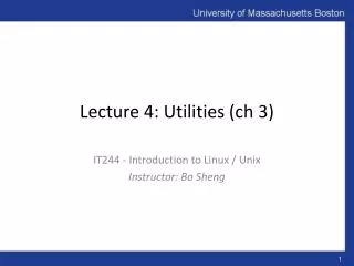
Break in insulation causes live to contact exposed metal case of Electrical Appliance
Assume 1000w appliance protected by a 5 amp fuse if the “earth loop impedance” (the effective resistance of the entire earth path) is assumed to be 1 the current when the fault occurs would rise to : a 5 amp fuse would virtually instantly blow. Note This calculation is not intended to indicate the technique to calculate the current flow under fault conditions but simply to indicate the potential massive surge in current due to a ‘short circuit’ to earth and how this disconnects the supply via the over-current protection. If the person was in contact with the appliance case at the time the fault occurred they may well not even know that the case become live for an instant due to the current taking the path of least resistance i.e. through the protective conductor to earth (circa 1) rather than through the person to earth (circa 1000).
To prevent this all extraneous conductive parts must be “cross bonded” i.e. they must have a protective conductor (earth cable) connected to the main earth terminal
Protection from shock By Residual Current Device (RCD) The use of RCDs are recognised as a means of providing additional protection in the event of failure of the provision for Basic Protection, as an additional means of Fault Protection, and to protect against carelessness by users.
Protection against Overload (Over-current Protection) All cables and flexes are sized to carry the current associated with the load it is connected to, the bigger the load the bigger the cable. If, by virtue of a fault or misuse the cable carries a current higher than it was designed for it will overheat, possibly to the point where a fire results. Over-current protection is designed to prevent this. The nominal setting of the over-current protective device must be greater than or equal to the design current of the load. The current-carrying capacity of the cables must be equal to or greater than the nominal setting of the over-current protective device. All cable must be protected by an appropriately sized and specified over-current protective device.
Types of Over-Current Protection Device: • High Breaking Capacity (HBC) fuse links BS 88-6 and BS EN 60269-2 Mainly commercial and industrial use. Give excellent short-circuit current protection. • HBC fuse links BS 1361 House service and consumer unit fuses. Not popular for use in consumer units; however, gives good short-circuit current protection. • MCBs (miniature circuit breakers) BS 3871, now superseded by BS EN 60898 CBs Domestic consumer units and commercial/industrial distribution boards. Very popular due to ease of operation. An alternative to, or replacement for, fuse links.
Cable and Containment Systems • A cabling system consists of: • Conductor • Insulation • Physical damage protection often called containment. • The most common forms of cable are:
Brown PVC insulated phase (or live) conductor Bare earth conductor Blue PVC insulated neutral conductor Grey or white PVC outer sheath Cables On domestic systems for small power and lighting PVC sheathed copper conductor cables are normally used. Lead sheathed and rubber insulated cable has long been superseded and, if encountered, must be replaced. PVC sheathed and insulated twin and earth cable
Electrical Wiring to BS 7671 PVC Sheath (insulator) Copper wire (conductor) Pre 2006 Colours Post 2006 Harmonised Colours Wiring Colours like voltages have been harmonised across Europe
Cable Tray & Basket: Used as physical protection for the distribution of multiple cables inside and outside non-domestic building. Cable tray is stronger and tends to be used for larger sized cables. Cable basket tends to be used for the containment of large numbers of smaller cables such as data networks, telephone and fire detection circuits.
Electrical Installations in Buildings • Electrical Loads: • The loads within a building are all the items that are electrically operated, these can be conveniently categorised as: • Lighting • Small power, socket outlets. • Small power, fixed appliances and specialist items • Lifts and escalators. • HVAC Plant and major specialist plant.
LIGHTING CIRCUITS • Usually configured to give Max load of 1kW per circuit for domestic property or 2kW for non domestic • Therefore the number of light fittings per circuit depends on the wattage of the lamps plus the losses from the lamp starting gear. 1000 watts at 230v draws a current of 4.6 Amps Circuit rating = 5A with a 6A protection device at distribution board/consumer unit For a non-domestic application a 10 amp protection device is likely to be used because of the higher loads. • Lighting circuits normally located in ceiling voids. • “Loop-in” system is the most common wiring method – minimum possible number of connections
LOOP-IN WIRING SYSTEM
POWER SOCKETS • Should be plentiful to stop overloading (see table on next slide) • Positioning • 150mm – 250mm above floor and surfaces • 750mm – 900mm (disabled)
Kitchen 6 Utility Room 3 Living rooms 8 Dining room 4 Master bedroom 6 Single bedrooms 3 Study bedrooms 4 Hall and landing 2 Garage / workshop 1 Bathroom (shaver socket) 1 LOCATION AND RECOMMENDED NUMBER OF SOCKETS • Connection using 32A rated ring circuits is the most common – ring circuits enables use of smaller cable (2.5mm2) • One ring circuit for upstairs • One for downstairs • Separate circuit for kitchen on newer premises
Small Power • Usually configured as a ring circuit • Small power circuits can be provided for known and predictable semi-permanent loads eg computer suits or variable and diverse loads eg domestic dwelling. • Usually each ring circuit should cover a MAXIMUM of 100m2 and maximum of 54m of cable. • Protected at 30 or 32 amp. Therefore: Watts = I x V. Watts = 32amp x 230V = 7360watts Typical appliance ratings…. Television 150 W, Vacuum cleaner 750 W , Hair drier 500 W, Microwave oven 850 W, Iron 1000 W, Food mixer, 500 W, Kettle 2500 W, Dishwasher 2000 W, Computer 150 W, Hand drier, 2500w, etc • Diversity can be applied, when appropriate, based on Highest single load + 75% of remaining load
Steel or plastic conduit buried in wall to protect PVC/PVC conductors. Conduit contains either individual conductors or twin & earth cable PVC/PVC conductors incorporating live, neutral and earth (twin and earth) run at ceiling level Twin Socket Outlet External wall Internal wall Conduit to ceiling level Consumer Unit RING CIRCUIT LAYOUT IN SINGLE STOREY BUILDING
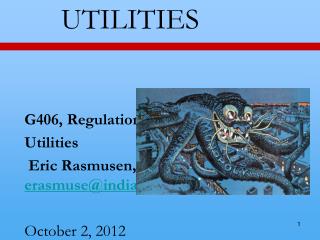
Circuits L1 L2 P1 P2 P3 P4 P5 P6 Combined in Consumer unit Distributionboard Main isolator switch Meter Services fuse and neutral link Incoming service cable SCHEMATIC OF DOMESTIC INCOMING ELECTRICAL SERVICE