Download
1 / 44
840 likes | 1.83k Vues
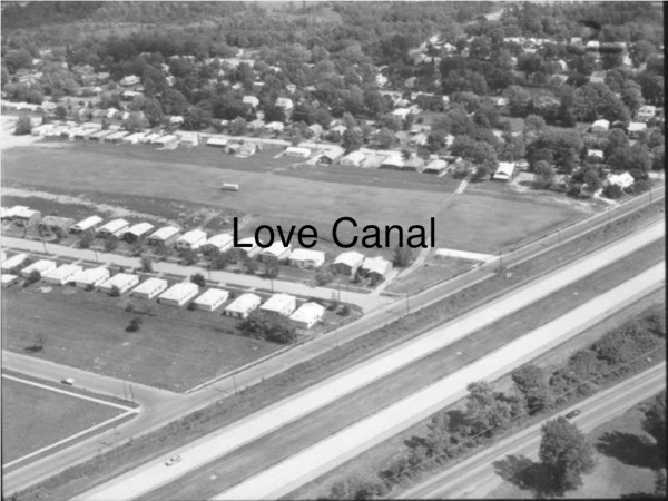
Canal Operations and Automation. Bert Clemmens U.S. Arid-Land Agricultural Research Center UDSA-ARS Maricopa, Arizona, USA. What have we learned so far?. Steady-state backwater curves are useful for understanding how canal systems function. Downstream influences can be transferred upstream.

E N D
Canal Operations and Automation Bert Clemmens U.S. Arid-Land Agricultural Research Center UDSA-ARS Maricopa, Arizona, USA
What have we learned so far? • Steady-state backwater curves are useful for understanding how canal systems function. Downstream influences can be transferred upstream. • Free-flow structures and sections of uniform flow (i.e., at normal depth) isolate downstream influences from transferring upstream.
Canal Operations are improved if operation of structure is simple. • Things that simplify operations: • Good flow measurement • Free-flow structures • long-crested weirs • Things that complicate operations • Lack of flow measurement • Uncertain structure hydraulics & operations • Intermediate, non-regulating structures
It is possible to determine wave travel times for operations from steady-state backwater curves (volume compensation) • Structure hydraulics have a big influence on how waves travel through canal pools. • Canals under backwater and weirs provide faster (and probably more predictable) response times.
Some things we didn’t cover • Typical operations can be considered upstream control, since we want to keep the water level on the upstream side of structures constant. • Long-crested weirs are being promoted because they reducing response times and keep water levels more constant • Automatic upstream level control is becoming more common.
Tail-Ender Problem • These approaches contribute to the tail-ended problem, where all the mismatches end up at the downstream end of the system.
Solving the Tail-Ender Problem • Good measurement and accounting keep right amount of water in canals and reduce the chance for serious mismatches. • This mean operators should keep track of and be accountable for mismatches • Remote manual operation can identify and correct the problem. (SCADA) • New methods for automatic downstream level control are being developed.
Old canal systems were not designed for accurate measurement, control and accounting • Canal control is difficult because: • Upstream changes are delayed downstream • Upstream changes arrive gradually • Pool volumes change with discharge, roughness, and depth at structure • Canal operators want steady flows and rigid schedules -- farmers want flexibility and responsiveness • Common problems result • Flow rates fluctuate • Flow rates may be too high or low • Operations are unresponsive to needs • Inadequate accounting for water entering and leaving canal
Manual Supervisory Control Additional Features • Incremental ( Relative ) Gate Flow Change • Flow rate control at headgates • Check-Structure Flow Balance Showing Accumulated Downstream Demands • Routing of known demand changes • Pool-Volume Balance to Help Determine Flow Mismatches • High/Low Water Level Limits Can Be Enforced Through Automatic Upstream Level Control
Flow Monitoring • Standard Supervisory Control Features using iFix Dynamics from Intellution, Inc. (MSIDD)
Flow Rate Control • Good Flow Measurement does not happen by accident • Check gates are usually not accurate measurement gates – but good incremental flow control is possible • Continuous monitoring of flows and/or levels/gate position is required • Turnout flow monitoring usually is based on assuming constant upstream water level • Only applicable for headgates or for check gates under centralized control
Incremental flow-rate control • iFix allows user-defined displays (CAIDD)
Software for Automated Canal Management -- SacMan Main features include: • Routing of known demand changes with volume compensation (similar to Canal de Provence and CAP). • Automatic control of flow rate at key locations. • Distant downstream water level feedback control to account for • flow measurement errors, • demand routing errors, & • unknown disturbances.
Personal Computer SacMan iFix SCADA iFix SacMan iFix RTU Process Demand Modbus Database - Database Driver SacMan Control SacMan Program Order iFix SCADA Monitor & Control Operator Software for Automated Canal Management -- SacMan
Components of control logic Feedforward controller DQff Flow controller Setpoint DQfb e Feedback controller y y y
Feedback control of Downstream Water Levels • PI Optimization with LQR • Multi-input multi-output optimization • Retains PI format for understandability • Based on incremental flow control • Extensively tested through simulation and considerable real-time testing • MPC optimization • Multi-input multi-output optimization • Black box format • Based on incremental flow control • Some testing through simulation and limited real-time testing • Can handle a wider variety of constraints
Flow changes are implemented by SacMan Control Program or printed for manual operation
Pool Flow Balance • SCADA screen shows • Actual flow at check structure • Current downstream demand at check structure • Operator can examine differences between actual and intended flows to identify control (or measurement) issues
Pool Volume Mismatches • With steady inflow and outflow, changes in pool water level indicate mismatches in net inflow rate (inflow – outflow) • SCADA screen shows flow mismatches • Operators can use flow mismatches to change flows between pools and route additional flow into the system • If water level is low and declining, operator needs to both increase flow and pool volume! • Note: these water-level based flow mismatches are meaningless when flow changes have recently been made
Software for Automated Canal ManagementSacMan Overall Control Strategy Manual Local Central Flow Monitoring Flow Control Demand Scheduling Incremental gate flow changes Out-of-Bounds control Pool Volume Mismatches Pool Flow Balance Control start-up Water-Level setpoint changes Alarms
Reachable Goal of Current Canal Automation Product Development • Water orders are entered into computer • SacMan routes flow changes through canal system based on volume compensation • Canal operator opens turnout gate at prescribed time • Water level errors are corrected with feedback control (new technology works!) • Headgate and check gate flow controllers maintain flow balances • If needed, main canal pool volumes are used to balance secondary canal volume errors
Maricopa-Stanfield Irrigation and Drainage District (MSIDD) • Approximately 87,000 Acres (35,000 Hectares ) • Construction completed in 1987 • Designed for supervisory control with optional automatic downstream control
WM Lateral An excellent test facility for canal automation research! • 90 cfs ( 2.5 m3/s) capacity • 5.4 miles (9 km) long • 8 pools • 10 turnouts (2 pumped) • 2 wells pumping in • emergency spill in last pool • ultrasonic meters on turnouts • canal travel time less than 2 hours • Main canal can tolerate changes in WM inflow
Testing during 2004 & 2005 • 30 day test period • 48 typical water orders • 2 atypical flow changes (power outgages) • Tested different upstream, LQR downstream control strategies and combinations • In 2005, tested Model Predictive Control
Typical test scenario • Routine operations (full control) • Water orders entered into SacMan Order • Schedule of gate flow changes made • Schedule posted to SacMan CP • SacMan CP changes flow setpoint • Check gate flow set every 2 minute • Operator delivers water to user • Feedback control adjustments every 10 minutes
Typical results- 20043 delivery changes routed automaticallyPI+-1 downstream controller (80% cap), pool 5 under level control
Feedback control of Downstream Water Levels • Multi-input multi-output optimization • Retains PI format for understandability • Based on incremental flow control • Extensively tested through simulation
Research (2002) on WM canal identified capabilities and limitation of various downstream water-level controllers Series of simple PI Controllers More Centralized PI+1-1 Controller
Feedback control tests 2004Simulated groundwater well failure PI+-1 and PIL+-More centralized controller spread out the disturbance
Summary • SacMan can control a canal under full automatic control • SacMan Order can effectively route deliveries under manual or automatic control • Performance depends on canal properties
Future Plans • Implementation at CAIDD (120 sites) is ongoing • SRP starting to test SacMan Order • New training tool for SCADA operators and canal automation testing has been developed
Off-line SCADA Training through Simulation Radio link sent to another computer that simulates RTU and Canal Flow
Sequence of Canal Automation Implementation Step 1: Remote, manual monitoring and control, using SCADA system Limitations: • Rely on operator judgment. • Wait-and-see approach. • Hard to control large network. • Transient flows are hard to control.
Sequence of Canal Automation Implementation Step 2: Independent, automated control of individual gates based on local water levels • Central control within SCADA (e.g. SRP) • Remote control with PLC (e.g. ITRC) or RTU. Limitations: • No coordination • Failures not recorded or observed • Tailender problems and spills • Wrong level controlled?
Sequence of Canal Automation Implementation Step 3: Centralized automated control, using SCADA and computer-driven logic. Limitations: • Accurate flow measurement or significant in-canal storage required. • Controls average water level rather than downstream water level (e.g. CAP).