Download
1 / 35
350 likes | 443 Vues
Design Activity of High Flux Test Module of IFMIF in Kyushu Univ. A. Shimizu@Kyushu Univ. Outline of IFMIF. Accelerator facilities. Target facilities. Test facilities. Supply 500cm 3 irradiation volume with 10 14 n/s ・ cm 2 (20dpa per year) neutron flux

E N D
Design Activity of High Flux Test Module of IFMIF in Kyushu Univ. A. Shimizu@Kyushu Univ.
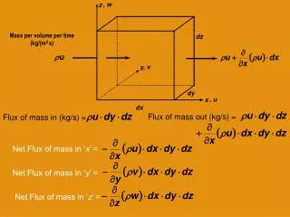
Outline of IFMIF Accelerator facilities Target facilities Test facilities • Supply 500cm3 irradiation volume with 1014n/s・cm2 (20dpa per year) neutron flux • Irradiation temperature: 250~1000℃ • Remove up to 10MW beam power by Lithium flow of 20m/s • Provide 40MeV, 250mA deuteron beam by 2 accelerator modules. • Irradiate D+ beams on Li target with beam footprint of 20cm(W) x 5cm(H) Li flow Deuteron beams Test piece Neutron irradiation Injector RFQ DTL Test Cell Heat exchanger PIE facilities Magnet pump • Engineering design over the whole system of IFMIF Design & Integration Mission • Qualification of candidate materials up to about full lifetime of anticipated use in a • fusion DEMO reactor. • Advanced material development for commercial reactors. • Calibration and validation of data generated from fission reactors and particle accelerators.
Test Cell Configuration shielding plug for high flux region for low & very low flux regions for medium flux region 2.5m D + Lithium target Li quench tank
Required performance for temperature control in He-cooled high flux test module Irradiation characteristics has strong dependency on temperature. Specimens must be kept at a constant temperature (250-1000℃) with acceptable error of less than 1%. Small irradiation volume of about 0.5 l must be assigned to specimens as large as possible. Space for cooling channels, heaters, insulations etc. should be minimized. The temperature control for specimens in HFTM is one of the most challenging issue in IFMIF project!!
Original design of test module Rig Test Pieces Capsule Gap T.C.
Buried location of T.C. from the capsule inner wall Large uncertainty of temperature measurement • Large uncertainty of temperature measurement is inevitable due to gap conditions and location of thermo-couple, if the T.C. is buried in capsule. • Effective gap conductance lgap varies as function of parameter f. • f means the volume fraction of occupation of gas (He) in the gap. • f =1 when the gap width is retained, but f can be change, for example, due to swelling. T.C. can not measure (estimate) the temperature of T.P. due to non-uniformity of temperature in T.P. and inherent uncertainty of measurement procedure. Estimation of uncertainty of temperature measurement
Change in design & derivation of HFTM • Ultimate purpose of HFTM Temperature control for irradiated specimens for long time periods in temperature window of 250-1000 deg. C with adequate volume for specimens. • Uncertainty of gap condition between specimens and capsules makes identification of specimen temperature very difficult. • Temperature difference of 100 K or so between actual and guessed temperature in specimens arises easily. NaK-bonding (EU) & He-bonding (JP) concept
Features of both design • NaK-bonding concept (EU) • Problem originated from gap condition is overcome due to high thermal conductivity of NaK filling the gap. Other problems arise • Nak is available only under 650 deg. C. • How to fill NaK into the gap of 0.1 mm or so? • How to treat activated NaK after irradiation test? • He-bonding concept (JP) • Whole temperature window up to 1000 deg. C. is feasible. • Cast-type capsule reduces the problem of gap. • Specimen temperature is guessed correctly by measuring dummy specimen temperature installed in the capsule.
EU design He-cooled HFTM with Chocolate-Plate-Shape Rig and Triple-Heater-Capsule Container with three compartments each with three rigs; Helium channels with a width of 1mm between the rigs
T.C. specimens <capsule inside> JP design -HFTM with horizontally-elongated capsules- coolant flow (He) • Capsules are elongated in the spanwise direction to fit the beam footprint. • Elongated capsule promote uniform temperature profile in themselves. • Specimens are housed in cast-type capsules. • Capsules are made of the same material as specimens to make nuclear heating in the capsules the same as specimens • Temperature of a capsule is measured to identify that of specimens housed in it. [mm] 200 50 neutron flux 50
Schematic of HFTM upper reflector He He rig upper reflector lateral reflector capsules lateral reflector bottom reflector bottom reflector straightener JP design EU design
Past activities @ Kyushu Univ. • Experimental tests • Temperature control experiment for one capsule using N2 gas loop • Pressure test for a module vessel as pressure boundary • Development of porous-type manifold for flow distribution into cooling channels • Numerical simulations • Thermal-hydraulic calculation using k-e turbulent model • Structural analysis for module vessel • Thermal-hydraulic calculation for expanded vessel using LES • Neutronics analysis in HFTM using PHITS • Other • Fabrication of full scale dummy in order to show the fabricability for the design of Kyushu univ. • Design of heater for temperature control
max. 30W/cm3 end neutron flux center Main achievement (1) • Temperature control in case of non-uniform nuclear heat generation was examined both experimentally and numerically. assumed spatial distribution of nuclear heating
203.0 34.6 183.0 50.0 25.0 131.5 16.5 25.0 cooling channel 295.0 12.6 1.0 [mm] coolant (N2) [Side View] [Front View] Test section insulation capsule Al
Photographs of test section 1000mm Test section Capsule and its supporters
159.8 t:1.4 79.8 14.8 25.0 15.0 17(W/cm2) 14(W/cm2) 19(W/cm2) Mica heater for non-uniform heating Ceramic heater for temperature control specimen for temperature measurement (Copper plate) Mica heater for non-uniform heating Inside view of heater for simulation of non-uniform nuclear heating Non-heating plate
70 15 t:1.3 Heater Heater 16.5 2.5 1.5 Ceramic heater for temperature control Ceramic heater for temperature control (thermal conductivity: 18[W/mK]) location of ceramic heaters Non-uniform Heating heater Photographic view of ceramic heater Non-heating plate Custom-made heaters could not be prepared and ready-made ones were used in the present run. heating region = 50mm ( 23 W/cm2)
Numerical simulation Conjugate solid/fluid heat transfer with turbulent flow (He) low Reynolds number k-e model for flow field (Abe et al., 1993) model for temperature field (Abe et al., 1995) Additional heater is introduced on the end of capsule. <Numerical conditions> Re = 939.3 (Um= 43.7 m/s) 1691 (78.9 m/s) 1880 (87.6 m/s ) 5636 ( 263 m/s) Tin = 50 deg.C, Pout = 0.3MPa (SUS316) adiabatic boundary symmetric boundary
Temperature distributions are quite improved by heaters for temperature control. The use of the end heater is effective. Temperature profile in capsule -simulation- heater heating
Main achievement (2) • Development of numerical codes for thermal-hydraulic, structural and neutronics analysis. • Thermal-hydraulic code using both k-e model & LES • Structural analysis with thermal effect considering finite deformation • Neutronics analysis using PHITS
ex.) Structural analysis for HFTM vessel deformation by pressure difference(Dp= 0. 3 MPa) wall thickness=1.0 mm • The center region of a wide wall is deflected largely due to pressure difference. • The largest displacement appears at the corner of the vessel on the symmetry boundary side in case with thermal effect. deformation by thermal effect (Re=19400) Mises stress
Structural analysis (previous study) 200 mm 50 mm computational domain Max. displacement of vessel v.s.Dp material; F82H
ex.) LES for expanded vessel Instantaneous velocity profile at x =0 A decrease in velocity is not only the vicinity of the expanded region but all round the cross-section. capsule wall vessel wall Instantaneous Temperature on capsule wall Temperature rise in case of expanded duct is remarkable in the center region.
Main achievement (3) • Development of a porous-type manifold for flow distribution • Because of its large flow resistance , porous media can make velocity profile uniform even in a short flow interval. • Uniform coolant flow achieved by porous media is equally distributed at bifurcation part. coolant flow Porous-type manifold testing volume ~50cm bifurcation part ceramic porous plate
Test section in detail anemometer capsule-array port 200 cross section of channel 1mm×200mm bifurcation part 40 measurement part 50 piesometer 525 straightener part 200 53.2 〔mm〕 200
Experimental mock-up -capsule-array port 1/1-scale of the HFTM !! cooling channel (1mm-width) side reflector-installation port (In this time, coolant flow through this port was not considered)
Effect of porous plates on velocity profile • For all Re, velocity profiles are remarkably improved by porous plates. • Increase in pressure drop due to increase in porous plates inserted is small. (Reduction of channel width at the bifurcation part is dominant.)
Fabrication of full scale dummy -overall view- coolant flow testing volume manifold
Fabrication of full scale dummy -each part- capsule capsule array • capsule array with top & bottom reflector capsule arrays in module with side reflectors
Capsule design specimens thermocouple cast-type capsule (the same material with specimens is preferred) Can be unified? plate heater (for temperature control)
Development of Capsule Heaters for HFTM with horizontally-elongated capsules • Demonstration of heater-printed capsule • Thermal conductivity of conventional heater is poor, which leads to excessive pumping power for coolant. • Unexpected occurrence of gap between heater and capsule under operation makes temperature of capsule uncontrollable. • The higher the heater power is, the bigger a required size of electric terminal.
1.0 1.0 15 200 16.4 Heater-printed Capsule -general view- Side Heater (600Wx2, 40W/cm2) End Heater (100Wx2, 40W/cm2) 1.0 1.0 16.5 [mm] 200 16.4
Heater-printed Capsule -cross-sectional view- Printed Heaters Multi-layered Ceramic Coating [mm] • Outer mounted heaters may become thermal barrier for cooling control. (Excess pumping power) • Small gap between heater and capsule wall should cause large non-uniformity of inner temperature distribution of capsule. (Uncontrollable situation) • Multi-layer coating technique has been already developed in the industrial world. • Possible combination of ceramic and heater materials is Magnesia-Alumina Spinel (MgAl2O4) and Mo. 1.0 Neutron Flux Heat Flux
dimension (mm) dimension (mm) 5×5×1.75t 25×25×1.75t working voltage working voltage 15V 100V capacity(room temp.) capacity(room temp.) 15W 555±20W power density power density 89W/cm2 60W/cm2 working temp. working temp. 1000℃Max 600℃Max withstand voltage withstand voltage 1500V(terminal-substrate) 1500V(terminal-substrate) Possible partner to develop capsule heaters • Sakaguchi E.H. VOC CORP. substrate of heating part (Almina) substrate of heating part (Almina) 2xf0.5 Ni lead-wire (polyimide tube) 2xf0.5 Ni lead-wire (polyimide tube) model name MS-1000 model name MS-M5