Download
1 / 49
550 likes | 891 Vues
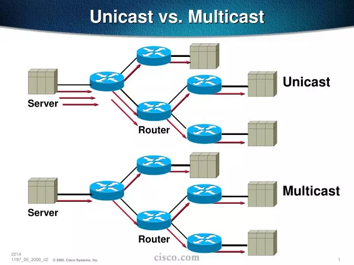
Unicast vs. Multicast. Unicast. Server. Router. Multicast. Server. Router. IP Multicast Group Addresses 224.0.0.0–239.255.255.255 Class “D” Address Space High order bits of 1st Octet = “1110” Reserved Link-local Addresses 224.0.0.0–224.0.0.255 Transmitted with TTL = 1 Examples:

E N D
Unicast vs. Multicast Unicast Server Router Multicast Server Router
IP Multicast Group Addresses 224.0.0.0–239.255.255.255 Class “D” Address Space High order bits of 1st Octet = “1110” Reserved Link-local Addresses 224.0.0.0–224.0.0.255 Transmitted with TTL = 1 Examples: 224.0.0.1 All systems on this subnet 224.0.0.2 All routers on this subnet 224.0.0.4 DVMRP routers 224.0.0.5 OSPF routers 224.0.0.13 PIMv2 Routers Multicast Addressing
Multicast Addressing IP Multicast MAC Address Mapping (FDDI and Ethernet) 32 Bits 28 Bits 1110 239.255.0.1 5 Bits Lost 01-00-5e-7f-00-01 25 Bits 23 Bits 48 Bits
Multicast Addressing IP Multicast MAC Address Mapping (FDDI & Ethernet) Be Aware of the 32:1 Address Overlap 32 - IP Multicast Addresses 224.1.1.1 224.129.1.1 225.1.1.1 225.129.1.1 . . . 238.1.1.1 238.129.1.1 239.1.1.1 239.129.1.1 1 - Multicast MAC Address (FDDI and Ethernet) 0x0100.5E01.0101
Host-Router Signaling: IGMP • How hosts tell routers about group membership • Routers solicit group membership from directly connected hosts • RFC 1112 specifies version 1 of IGMP • Supported on Windows 95 • RFC 2236 specifies version 2 of IGMP • Supported on latest service pack for Windows and most UNIX systems • IGMP version 3 is specified in IETF draft • draft-ietf-idmr-igmp-v3-03.txt
Host sends IGMP Report to join group 224.1.1.1 H3 H3 Report Host-Router Signaling: IGMP Joining a Group H2 H1
Router sends periodic Queries to 224.0.0.1 224.1.1.1 224.1.1.1 224.1.1.1 H2 H3 H1 X X Suppressed Report Suppressed Query Host-Router Signaling: IGMP Maintaining a Group • One member per group per subnet reports • Other members suppress reports
224.1.1.1 H3 Leave to 224.0.0.2 #1 Group Specific Query to 224.1.1.1 #2 Host-Router Signaling: IGMP Leaving a Group (IGMPv2) H2 H3 H1 • Host sends Leave message to 224.0.02 • Router sends Group specific query to 224.1.1.1 • No IGMP Report is received within ~3 seconds • Group 224.1.1.1 times out
Multicast Distribution Trees Shortest Path or Source Distribution Tree Source 1 Notation: (S, G) S = Source G = Group Source 2 A B F D C E Receiver 1 Receiver 2
Multicast Distribution Trees Shortest Path or Source Distribution Tree Source 1 Notation: (S, G) S = Source G = Group Source 2 A B F D C E Receiver 1 Receiver 2
Shared Tree Multicast Distribution Trees Shared Distribution Tree Notation: (*, G) * = All Sources G = Group A B F D (RP) (RP) PIM Rendezvous Point C E Receiver 1 Receiver 2
Source 1 Source 2 Source Tree Multicast Distribution Trees Shared Distribution Tree Notation: (*, G) * = All Sources G = Group A B F D (RP) (RP) PIM Rendezvous Point C E Shared Tree Receiver 1 Receiver 2
Multicast Distribution Trees • Source or Shortest Path trees Uses more memory O(S x G) but you get optimal paths from source to all receivers; minimizes delay • Shared trees Uses less memory O(G) but you may get sub-optimal paths from source to all receivers; may introduce extra delay Characteristics of Distribution Trees
Multicast Forwarding • Multicast Routing is backwards from Unicast Routing • Unicast Routing is concerned about where the packet is going. • Multicast Routing is concerned about where the packet came from. • Multicast Routing uses “Reverse Path Forwarding”
Multicast Forwarding Reverse Path Forwarding (RPF) • What is RPF? • A router forwards a multicast datagram only if received on the up stream interface to the source (i.e. it follows the distribution tree). • The RPF Check • The routing table used for multicasting is checked against the “source” IP address in the packet. • If the datagram arrived on the interface specified in the routing table for the source address; then the RPF check succeeds. • Otherwise, the RPF Check fails.
Multicast Forwarding Example: RPF Checking Source151.10.3.21 RPF Check Fails Packet arrived on wrong interface! Mcast Packets
Multicast Packet from Source 151.10.3.21 X Packet Arrived on Wrong Interface! Discard Packet! Multicast Forwarding A closer look: RPF Check Fails S0 RPF Check Fails! S1 S2 Unicast Route Table Network Interface 151.10.0.0/16 S1 198.14.32.0/24 S0 204.1.16.0/24 E0 E0 S1
Multicast Packet from Source 151.10.3.21 Packet Arrived on Correct Interface! Multicast Forwarding A closer look:RPF Check Succeeds S0 S1 S2 RPF Check Succeeds! E0 Unicast Route Table Network Interface 151.10.0.0/16 S1 198.14.32.0/24 S0 204.1.16.0/24 E0 S1 Forward out all outgoing interfaces.(i. e. down the distribution tree)
Multicast vs. Unicast Routing Multicast Routing is not unicast routing. You have to think of it differently. It is not like OSPF. It is not like RIP. It is not like anything you may be familiar with.
Types of Multicast Protocols • Dense-mode • Uses “Push” Model • Traffic Flooded throughout network • Pruned back where it is unwanted • Flood & Prune behavior (typically every 3 minutes) • Sparse-mode • Uses “Pull” Model • Traffic sent only to where it is requested • Explicit Join behavior
Multicast Protocol Overview • Currently, there are four multicast routing protocols: • DVMRPv3 (Internet-draft) • DVMRPv1 (RFC 1075) is obsolete and unused. A variant is currently implemented • MOSPF (RFC 1584) • PIM-DM (Internet-draft) • PIM-SM (RFC 2362- v2) • Others (CBT, OCBT, QOSMIC, SM, etc.)
DVMRP Overview • Dense Mode Protocol • Distance vector-based • Similar to RIP • Infinity = 32 hops • Subnet masks in route advertisements • DVMRP Routes used: • For RPF Check • To build Truncated Broadcast Trees (TBTs) • Uses special “Poison-Reverse” mechanism • Uses Flood and Prune operation • Traffic initially flooded down TBT’s • TBT branches are pruned where traffic is unwanted. • Prunes periodically time-out causing reflooding.
mrouted mrouted mrouted 33 1 1 3 33 35 1 2 mrouted mrouted mrouted 34 35 2 3 mrouted 2 n m DVMRP—Source Trees • Truncated Broadcast Trees Are Built using Best DVMRP Metrics Back to Source Network. • Lowest IP Address Used in Case of a Tie.(Note: IP Address of D < C < B < A) Source Network A B X D E C Y Route for source network of metric “n” Poison reverse (metric + infinity) sent to upstream “parent” router. Router depends on “parent” to receive traffic for this source. Resulting Truncated Broadcast Tree for Source Network
mrouted mrouted mrouted DVMRP—Source Trees Forwarding onto Multi-access Networks Network X • Both B and C have routes to network X. • To avoid duplicates, only one router can be “Designated Forwarder” for network X. • Router with best metric is elected as the “Designated Forwarder”. • Lowest IP address used as tie-breaker. • Router C wins in this example. A 1 1 C B 2 2 (Note: IP Address of C < B ) n Route advertisement for network X of metric “n”
mrouted mrouted mrouted mrouted mrouted mrouted mrouted DVMRP—Source Trees Source Network “S1” Resulting Truncated Broadcast Tree for Source Network “S1” A B X D E C Y S1 Source Tree
mrouted mrouted mrouted mrouted mrouted mrouted mrouted DVMRP—Source Trees Each Source Network has it’s Own Truncated Broadcast Tree A B X E D C Y Note: IP Address of D < C < B < A S2 Source Tree Source “S2”
mrouted mrouted mrouted mrouted mrouted mrouted mrouted DVMRP—Flood & Prune Source “S” Initial Flooding of (S, G) Multicast Packets Down Truncated Broadcast Tree A B X 1 D E C Y Receiver 1 (Group “G”) Truncated Broadcast Tree based on DVMRP route metrics (S, G) Multicast Packet Flow
mrouted mrouted mrouted Prune mrouted mrouted mrouted mrouted DVMRP—Flood & Prune Source “S” Routers C is a Leaf Node so it sends an “(S, G) Prune” Message A B Router B Prunes interface. X D E C Y Receiver 1 (Group “G”) Truncated Broadcast Tree based on DVMRP route metrics (S, G) Multicast Packet Flow
Prune mrouted mrouted mrouted mrouted mrouted mrouted Prune mrouted DVMRP—Flood & Prune Source “S” Routers X, and Y are also Leaf Nodes so they send “Prune (S, G)” Messages A B Router E prunes interface. X D E C Y Receiver 1 (Group “G”) Truncated Broadcast Tree based on DVMRP route metrics (S, G) Multicast Packet Flow
mrouted mrouted mrouted Prune mrouted mrouted mrouted mrouted DVMRP—Flood & Prune Source “S” Router E is now a Leaf Node; it sends an (S, G) Prune message. A B Router D prunes interface. X D E C Y Receiver 1 (Group “G”) Truncated Broadcast Tree based on DVMRP route metrics (S, G) Multicast Packet Flow
mrouted mrouted mrouted mrouted mrouted mrouted mrouted DVMRP—Flood & Prune Source “S” A B Final Pruned State X D E C Y Receiver 1 (Group “G”) Truncated Broadcast Tree based on DVMRP route metrics (S, G) Multicast Packet Flow
mrouted mrouted mrouted Graft mrouted mrouted mrouted mrouted DVMRP—Grafting Source “S” Receiver 2 joins Group “G” Router Y sends a “Graft (S, G)” Message A B X D E C Y Receiver 1 (Group “G”) Receiver 2 (Group “G”) Truncated Broadcast Tree based on DVMRP route metrics (S, G) Multicast Packet Flow
mrouted mrouted mrouted Graft mrouted mrouted mrouted mrouted Graft-Ack DVMRP—Grafting Source “S” Router E Responds with a “Graft-Ack” A B Sends its Own “Graft (S, G) Message X D E C Y Receiver 1 (Group “G”) Receiver 2 (Group “G”) Truncated Broadcast Tree based on DVMRP route metrics (S, G) Multicast Packet Flow
mrouted mrouted mrouted Graft-Ack mrouted mrouted mrouted mrouted DVMRP—Grafting Source “S” Router D Responds with a “Graft-Ack” Begins Forwarding (S, G) Packets A B X D E C Y Receiver 1 (Group “G”) Receiver 2 (Group “G”) Truncated Broadcast Tree based on DVMRP route metrics (S, G) Multicast Packet Flow
PIM-DM • Protocol Independent • Supports all underlying unicast routing protocols including: static, RIP, IGRP, EIGRP, IS-IS, BGP, and OSPF • Uses reverse path forwarding • Floods network and prunes back based on multicast group membership • Assert mechanism used to prune off redundant flows • Appropriate for... • Smaller implementations and pilot networks
Multicast Packets PIM-DM Flood & Prune Initial Flooding Source (S, G) State created in every router in the network! Receiver
Multicast Packets Prune Messages PIM-DM Flood & Prune Pruning Unwanted Traffic Source Receiver
Multicast Packets PIM-DM Flood & Prune Results After Pruning Source (S, G) State still exists in every router in the network! Flood & Prune process repeats every 3 minutes!!! Receiver
PIM-SM (RFC 2362) • Supports both source and shared trees • Assumes no hosts want multicast traffic unless they specifically ask for it • Uses a Rendezvous Point (RP) • Senders and Receivers “rendezvous” at this point to learn of each others existence. • Senders are “registered” with RP by their first-hop router. • Receivers are “joined” to the Shared Tree (rooted at the RP) by their local Designated Router (DR). • Appropriate for… • Wide scale deployment for both densely and sparsely populated groups in the enterprise • Optimal choice for all production networks regardless of size and membership density.
(*, G) Join Shared Tree PIM-SM Shared Tree Join RP (*, G) State created only along the Shared Tree. Receiver
Source (S, G) Register (unicast) (S, G) Join Traffic Flow Source Tree PIM-SM Sender Registration RP (S, G) State created only along the Source Tree. Shared Tree Receiver
Source (S, G) Register (unicast) Traffic Flow Source Tree (S, G) Register-Stop (unicast) PIM-SM Sender Registration RP (S, G) traffic begins arriving at the RP via the Source tree. Shared Tree RP sends a Register-Stop back to the first-hop router to stop the Register process. Receiver
Source Traffic Flow Source Tree PIM-SM Sender Registration RP Source traffic flows nativelyalong SPT to RP. From RP, traffic flows downthe Shared Tree to Receivers. Shared Tree Receiver
Source (S, G) Join Traffic Flow Source Tree PIM-SM SPT Switchover RP Last-hop router joins the Source Tree. Shared Tree Additional (S, G) State is created along new part of the Source Tree. Receiver
Source Traffic Flow Source Tree (S, G)RP-bit Prune PIM-SM SPT Switchover RP Traffic begins flowing down the new branch of the Source Tree. Shared Tree Additional (S, G) State is created along along the Shared Tree to prune off (S, G) traffic. Receiver
Source Traffic Flow Source Tree PIM-SM SPT Switchover RP (S, G) Traffic flow is now pruned off of the Shared Tree and is flowing to the Receiver via the Source Tree. Shared Tree Receiver
Source Traffic Flow Source Tree (S, G) Prune PIM-SM SPT Switchover RP (S, G) traffic flow is no longer needed by the RP so it Prunes the flow of (S, G) traffic. Shared Tree Receiver
Source Traffic Flow Source Tree PIM-SM SPT Switchover RP (S, G) Traffic flow is now only flowing to the Receiver via a single branch of the Source Tree. Shared Tree Receiver
Documentation • EFT/Beta Site Web Page: ftp://ftpeng.cisco.com/ipmulticast.html